Repeated Thomas algorithm, pointwise version
| Two-sided elimination method, pointwise version | |
| Sequential algorithm | |
| Serial complexity | [math]8n-2[/math] |
| Input data | [math]4n-2[/math] |
| Output data | [math]n[/math] |
| Parallel algorithm | |
| Parallel form height | [math]2.5n-1[/math] |
| Parallel form width | [math]4[/math] |
Primary authors of this description: A.V.Frolov, Vad.V.Voevodin (Section 2.2), A.M.Teplov (Section 2.4)
Contents
- 1 Properties and structure of the algorithm
- 1.1 General description of the algorithm
- 1.2 Mathematical description of the algorithm
- 1.3 Computational kernel of the algorithm
- 1.4 Macro structure of the algorithm
- 1.5 Implementation scheme of the serial algorithm
- 1.6 Serial complexity of the algorithm
- 1.7 Information graph
- 1.8 Parallelization resource of the algorithm
- 1.9 Input and output data of the algorithm
- 1.10 Properties of the algorithm
- 2 Software implementation of the algorithm
- 2.1 Implementation peculiarities of the serial algorithm
- 2.2 Locality of data and computations
- 2.3 Possible methods and considerations for parallel implementation of the algorithm
- 2.4 Scalability of the algorithm and its implementations
- 2.5 Dynamic characteristics and efficiency of the algorithm implementation
- 2.6 Conclusions for different classes of computer architecture
- 2.7 Existing implementations of the algorithm
- 3 References
1 Properties and structure of the algorithm
1.1 General description of the algorithm
The two-sided elimination method is a variant of Gaussian elimination used for solving a system of linear algebraic equations (SLAE) [1][2] Ax = b, where
- [math] A = \begin{bmatrix} a_{11} & a_{12} & 0 & \cdots & \cdots & 0 \\ a_{21} & a_{22} & a_{23}& \cdots & \cdots & 0 \\ 0 & a_{32} & a_{33} & \cdots & \cdots & 0 \\ \vdots & \vdots & \ddots & \ddots & \ddots & 0 \\ 0 & \cdots & \cdots & a_{n-1 n-2} & a_{n-1 n-1} & a_{n-1 n} \\ 0 & \cdots & \cdots & 0 & a_{n n-1} & a_{n n} \\ \end{bmatrix}, x = \begin{bmatrix} x_{1} \\ x_{2} \\ \vdots \\ x_{n} \\ \end{bmatrix}, b = \begin{bmatrix} b_{1} \\ b_{2} \\ \vdots \\ b_{n} \\ \end{bmatrix} [/math]
However, presentations of the elimination method [3] often use a different notation and a numbering for the right-hand side and matrix of the system. For instance, the above SLAE can be written as
- [math] A = \begin{bmatrix} c_{0} & -b_{0} & 0 & \cdots & \cdots & 0 \\ -a_{1} & c_{1} & -b_{1} & \cdots & \cdots & 0 \\ 0 & -a_{2} & c_{2} & \cdots & \cdots & 0 \\ \vdots & \vdots & \ddots & \ddots & \ddots & 0 \\ 0 & \cdots & \cdots & -a_{N-1} & c_{N-1} & -b_{N-1} \\ 0 & \cdots & \cdots & 0 & -a_{N} & c_{N} \\ \end{bmatrix}\begin{bmatrix} y_{0} \\ y_{1} \\ \vdots \\ y_{N} \\ \end{bmatrix} = \begin{bmatrix} f_{0} \\ f_{1} \\ \vdots \\ f_{N} \\ \end{bmatrix} [/math]
(here, N=n-1). If each equation is written separately, then we have
[math]c_{0} y_{0} - b_{0} y_{1} = f_{0}[/math],
[math]-a_{i} y_{i-1} + c_{i} y_{i} - b_{i} y_{i+1} = f_{i}, 1 \le i \le N-1[/math],
[math]-a_{N} y_{N-1} + c_{N} y_{N} = f_{N}[/math].
Similarly to the classical (monotone) elimination method, the two-sided variant eliminates unknowns in a system; however, unlike the former, it simultaneously performs elimination from both corners (the upper and lower ones) of the SLAE. In principle, the two-sided elimination can be regarded as the simplest version of the reduction method (in which m = 1 and monotone eliminations are conducted in opposite directions).
1.2 Mathematical description of the algorithm
Let m be the index of an equation which is the meeting point of two branches (the upper and lower ones) of the forward elimination path.
In the notation introduced above, the forward elimination path consists in calculating the elimination coefficients top down
[math]\alpha_{1} = b_{0}/c_{0}[/math],
[math]\beta_{1} = f_{0}/c_{0}, [/math]
[math]\alpha_{i+1} = b_{i}/(c_{i}-a_{i}\alpha_{i}), \quad i = 1, 2, \cdots , m-1[/math],
[math]\beta_{i+1} = (f_{i}+a_{i}\beta_{i})/(c_{i}-a_{i}\alpha_{i}), \quad i = 1, 2, \cdots , m-1. [/math]
and bottom up:
[math]\xi_{N} = a_{N}/c_{N}[/math],
[math]\eta_{N} = f_{N}/c_{N}[/math],
[math]\xi_{i} = a_{i}/(c_{i}-b_{i}\xi_{i+1})[/math], [math]\quad i = N-1, N-2, \cdots , m[/math],
[math]\eta_{i} = (f_{i}+b_{i}\eta_{i+1})/(c_{i}-b_{i}\xi_{i+1})[/math], [math]\quad i = N-1, N-2, \cdots , m. [/math]
Conventional descriptions of two-sided elimination (see [3]) do not usually give a formula for [math]y_{m-1}[/math]. This component is calculated later in the backward elimination path. However, by postponing the calculation of [math]y_{m-1}[/math] till the moment when [math]y_{m}[/math] is already calculated, we extend the critical path of the graph. Meanwhile, both components can be calculated simultaneously and almost indepependently one from the other.
1.3 Computational kernel of the algorithm
The computational kernel of this algorithm can be thought of as compiled of two parts (forward and backward elimination paths), as was also the case with the classical monotone elimination method. However, the width of both is twice as large compared to the monotone variant. The kernel of the forward path consists of two independent sequences of divisions, multiplications, and additions/subtractions. The kernel of the backward path contains only two independent sequences of multiplications and additions.
1.4 Macro structure of the algorithm
The macro structure of this algorithm can be represented as the combination of the forward and backward elimination paths. In addition, the forward path can be split into two macro units, namely, the forward paths of both right- and left-eliminations executed simultaneously, that is, in parallel, for two halves of the SLAE. The backward path can also be split into two macro units, namely, the backward paths of both right- and left-eliminations executed simultaneously, that is, in parallel, for two halves of the SLAE.
1.5 Implementation scheme of the serial algorithm
The method is executed as the following sequence of steps:
1. Initialize the forward elimination path:
[math]\alpha_{1} = b_{0}/c_{0}[/math],
[math]\beta_{1} = f_{0}/c_{0}[/math],
[math]\xi_{N} = a_{N}/c_{N}[/math],
[math]\eta_{1} = f_{N}/c_{N}[/math].
2. Execute the forward path formulas:
[math]\alpha_{i+1} = b_{i}/(c_{i}-a_{i}\alpha_{i})[/math], [math]\quad i = 1, 2, \cdots , m-1[/math],
[math]\beta_{i+1} = (f_{i}+a_{i}\beta_{i})/(c_{i}-a_{i}\alpha_{i})[/math], [math]\quad i = 1, 2, \cdots , m-1[/math],
[math]\xi_{i} = a_{i}/(c_{i}-b_{i}\xi_{i+1})[/math], [math]\quad i = N-1, N-2, \cdots , m[/math],
[math]\eta_{i} = (f_{i}+b_{i}\eta_{i+1})/(c_{i}-b_{i}\xi_{i+1})[/math], [math]\quad i = N-1, N-2, \cdots , m[/math].
3. Initialize the backward elimination path:
[math]y_{m-1} = (\beta_{m}+\alpha_{m}\eta_{m})/(1-\xi_{m}\alpha_{m})[/math],
[math]y_{m} = (\eta_{m}+\xi_{m}\beta_{m})/(1-\xi_{m}\alpha_{m})[/math].
4. Execute the backward path formulas:
[math]y_{i} = \alpha_{i+1} y_{i+1} + \beta_{i+1}[/math], [math]\quad i = m-1, m-2, \cdots , 1, 0[/math],
[math]y_{i+1} = \xi_{i+1} y_{i} + \eta_{i+1}[/math], [math]\quad i = m, m+1, \cdots , N-1[/math].
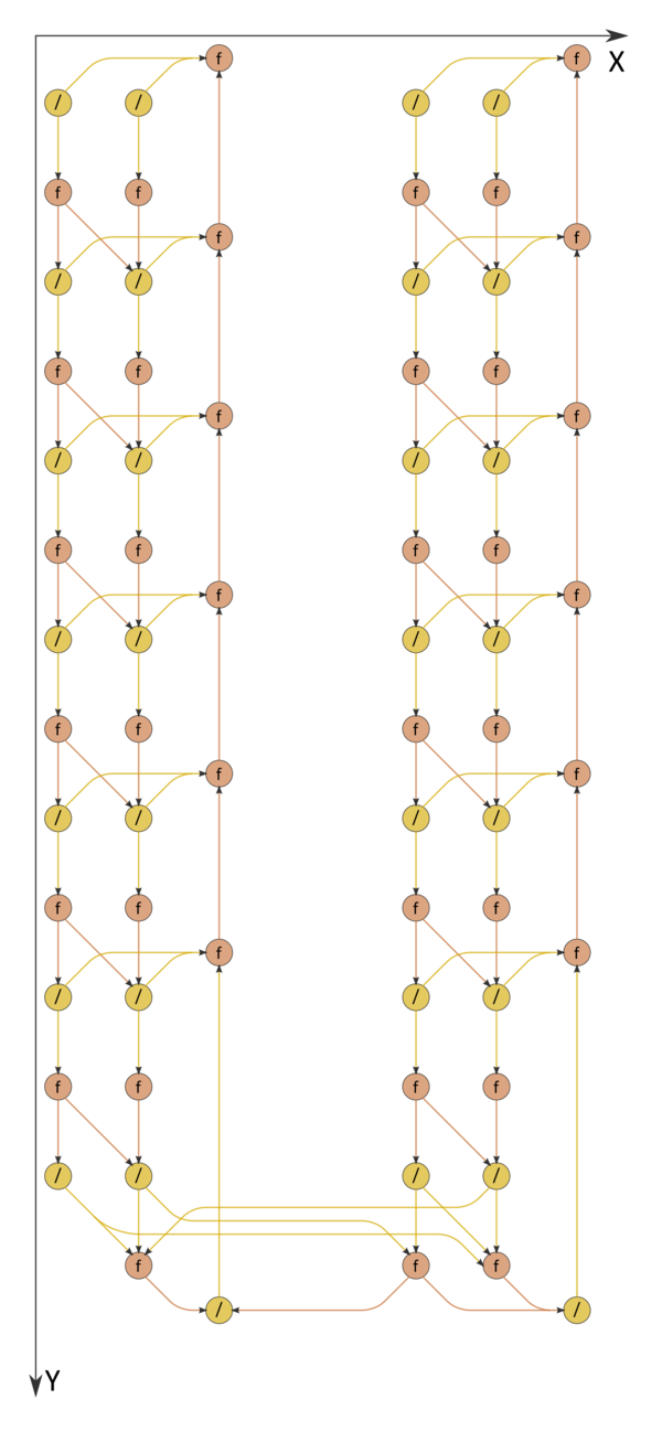
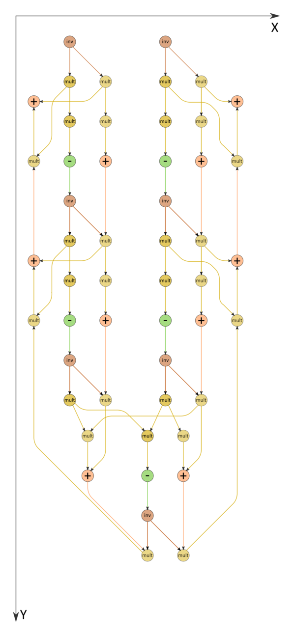
The formulas of the forward path contain double divisions by the same expressions. These divisions can be replaced by the calculation of reciprocal numbers succeeded by the multiplication by these numbers (see fig. 2).
1.6 Serial complexity of the algorithm
Consider a tridiagonal SLAE consisting of n equations with n unknowns. The two-sided elimination method as applied to solving such a SLAE in its (fastest) serial form requires
2n+2 divisions,
3n-2 additions/subtractions, and
3n-2 multiplications.
Thus, in terms of serial complexity, the two-sided elimination method is qualified as a linear complexity algorithm.
1.7 Information graph
The information graph of the two-sided elimination method is shown in fig. 1. It is obvious that the graph is parallel, the degree of parallelism being at most four and two at its forward and backward paths, respectively. During the forward path, the two branches and also two of their sub-branches (namely, the left sub-branch, corresponding to the matrix decomposition, and the right branch, responsible for the solution of the first bidiagonal system) can be executed in parallel.The right sub-branches correspond to the backward path. It is evident from the figure that not only the mathematical content of this process but also the structure of the algorithm graph and the direction of the corresponding data flows are in complete agreement with the appellation "backward path." The variant with divisions replaced by reciprocal number calculations is illustrated by the graph in fig. 2.
1.8 Parallelization resource of the algorithm
Both branches of the forward elimination path are executed in parallel when [math]N=2m-1[/math], that is, when [math]n=2m[/math]. Then the two-sided elimination method requires that the following layers be executed:
[math]m+1[/math] division layers (all the layers except for one contain 4 divisions, and the remaining layer contains 2 divisions),
[math]2m-1[/math] multiplication layers and the same number of addition/subtraction layers ([math]m-1[/math] layers contain four operations, another [math]m-1[/math] layers contain two operations, and the remaining layer contains three operations).
Thus, in terms of the parallel form height, the two-sided elimination method is qualified as an algorithm of complexity O(n). In terms of the parallel form width, its complexity is 4.
Two branches cannot be synchronized if [math]n[/math] is odd. It is therefore preferable to choose problems of even dimensions.
1.9 Input and output data of the algorithm
Input data: tridiagonal matrix A (with entries a_{ij}), vector b (with components b_{i}).
Output data: vector x (with components x_{i}).
Size of the output data: n.
1.10 Properties of the algorithm
It is clearly seen that the ratio of the serial to parallel complexity is a constant (which is less than 4).
The computational power of the algorithm, understood as the ratio of the number of operations to the total size of the input and output data, is also a constant.
Within the framework of the chosen version, the algorithm is completely determined.
Similarly to the monotone elimination, the two-sided elimination method is traditionally used for solving SLAEs with diagonally dominant coefficient matrices. For such systems, the algorithm is guaranteed to be stable. If several systems with the same coefficient matrix have to be solved, then the branches that calculate elimination coefficients may not to be repeated. In such cases, the variant with divisions replaced by reciprocal number calculations is preferable.
2 Software implementation of the algorithm
2.1 Implementation peculiarities of the serial algorithm
Depending on how the calculations are organized, one can use different modes of storing the coefficient matrix of a SLAE (as a single array with three rows or three distinct arrays) and different ways of storing the calculated elimination coefficients (in locations of the already used matrix entries or separately).
Let us give an example of a subroutine implementing the two-sided elimination method. Here, all the matrix entries are stored in a single array; moreover, the entries neighboring in a row are located closely to each other, and the calculated coefficients are stored in locations of the original matrix entries that are no longer needed.
      subroutine vprogm (a,x,N) ! N=2m-1
      real a(3,0:N), x(0:N)

      m=(N+1)/2

      a(2,0)=1./a(2,0)
      a(2,N)=1./a(2,N)

      a(3,0)=-a(3,0)*a(2,0) ! alpha 1
      a(1,N)=-a(1,N)*a(2,N) ! xi N

      x(0)=x(0)*a(2,0) ! beta 1
      x(N)=x(N)*a(2,N) ! eta N

      do 10 i=1,m-1

        a(2,i)=1./(a(2,i)+a(1,i)*a(2,i-1))
        a(2,N-i)=1./(a(2,N-i)+a(3,N-i)*a(2,N-i+1))

        a(3,i) = -a(3,i)*a(2,i) ! alpha i+1
        a(1,N-i) = -a(1,N-i)*a(2,N-i) ! xi N-i

        x(i)=(x(i)-a(1,i)*x(i-1))*a(2,i) ! beta i+1
        x(N-i)=(x(N-i)-a(3,N-i)*x(N-i+1))* a(2,N-i) ! eta N-i

  10  continue

      a(1,0)=1./(1.-a(1,m)*a(3,m-1))
      bb=x(m-1)
      ee=x(m)
      x(m-1)=(bb+a(3,m-1)*ee))*a(1,0) ! y m-1
      x(m) = (ee+a(1,m)*bb)*a(1,0) ! y m

      do 20 i=m+1,N
        x(i)=a(1,i)*x(i-1)+x(i) ! y i
        x(N-i)=a(3,N-i)*x(N-i+1)+x(i) ! y N-i
  20  continue
      return
      end
2.2 Locality of data and computations
One can see from the algorithm graph that the spatial locality of the data is fair. Indeed, all the arguments needed for an operation are calculated "nearby." However, the temporal locality is not as good. Suppose that the cache cannot hold all the problem data. Then repeated cache misses will occur while performing calculations in the "upper left" and "lower right" corners of a SLAE. Thus, one of the recommendations to application engineers using the two-sided elimination method is as follows: Arrange the calculations so that all the elimination paths are sufficiently short and their data can be placed in the cache.
The two-sided elimination method is an example of a serial algorithm with the locality of computations so high that it even becomes excessive when the two basic branches are implemented separately by different cores or serially one after the other [4]. Computational cores of processors virtually cannot use their superscalar capabilities because the data needed by the basic operations of this method are produced by immediately preceding operations. This sharply deteriorates the performance of the method even for modern single-processor and single-core systems. That is why, in the above subroutine, both branches (of the forward, as well as the backward, elimination path) are brought together into a single loop. However, since the efficiency remains low, the only advantage is attained over the exceedingly local monotone elimination.
2.2.1 Locality of implementation
2.2.1.1 Structure of memory access and a qualitative estimation of locality
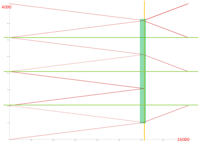
Figure 3 presents the memory access profile for an implementation of the pointwise version of two-sided elimination method. This profile consists of two stages separated by the yellow line. Four arrays are accessed at each stage. Accesses to different arrays are separated by green horizontal lines. Judging from the general profile, one can expect that about the same accesses occur at the first stage to all arrays. In each case, two concurrently executed serial accesses are formed. One of them is arranged in increasing order of the array entries, while the other is arranged in decreasing order.
At the second stage, profiles are different for different arrays; however, they again resemble conventional serial accesses. If this is true, then this profile has a high spatial locality (accesses to neighboring entries are close to each other) but a fairly low temporal locality (a repeated usage of the data is virtually missing). Let us look at the profile in more detail in order to verify our conclusions.
A fragment of the general profile (set out in green in fig. 3) is shown in fig. 4. One can see that the accesses to four arrays do indeed have a regular structure and neighboring entries are indeed accessed at close moments. It is, however, difficult to determine up to isolated accesses how these four separate profiles are structured.
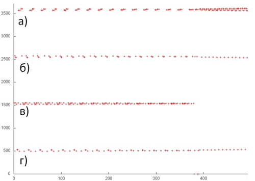
The profiles shown in fig. 4 are inspected more closely in fig. 5. At this scale, one can see that, on the whole, all the profiles do indeed consist of serial accesses, but a different number of references is made at each step of the access. The profile in fig. 5a references the current entry and the preceding one, while the profile in fig. 5b seems to reference also the next entry. The profiles 5c and 5d are structured somewhat simpler because only one serial access performs two references per step.
Based on information obtained, one can infer that the access locality is even better than what was suggested in the discussion of the general profile. The reason is that the same data are often used several times in succession, which improves both spatial and temporal locality.
2.2.1.2 Quantitative estimation of locality
The basic fragment of the implementation used for obtaining quantitative estimates is given here [1] (the Kernel function). The start-up parameters are described here [2].
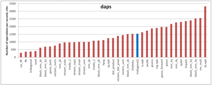
The first estimate is produced on the basis of daps, which estimates the number of memory accesses (reading and writing) per second. This characteristic, used for the interaction with memory, is an analog of the flops estimate. It largely estimates the performance of this interaction rather than locality. Nevertheless, this characteristic (in particular, its comparison with the next characteristic cvg) is a good source of information.
Figure 6 presents the values of daps for implementations of popular algorithms. They are arranged in increasing order (in general, the larger daps, the higher efficiency). On the whole, the daps value of this subroutine indicates a fairly high performance of memory interaction, which corresponds to our expectations stated in the locality description given above.
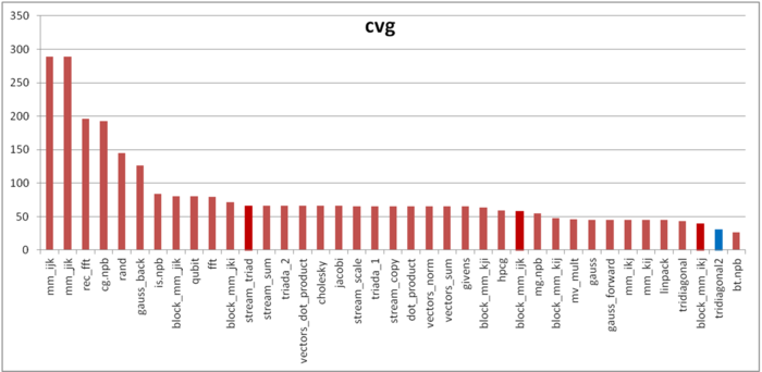
The second characteristic, called cvg, is intended for obtaining a locality estimate that would be more machine independent. It determines how often a program needs to fetch data to the cache memory. Accordingly, smaller values of cvg correspond to less often fetch operations and better locality.
Figure 7 presents the values of cvg for the same set of implementations. They are arranged in decreasing order (in general, the smaller cvg, the higher locality). The cvg value of this subroutine is quite high; it is even higher than in the case of the Linpack test. One can notice a marked difference between the daps and cvg estimates. It is possible that the reasons for this difference are the same as for the conventional elimination method. The latter are described here.
2.3 Possible methods and considerations for parallel implementation of the algorithm
The two-sided elimination method was initially designed for the case where one only wants to know some component of the solution close to its "middle", while the other components are not needed (the so-called "partial solution"). With the advent of parallel computers, it was found that the method has a modest parallelization resource; namely, an acceleration is obtained if its upper and lower branches are distributed between two processors. However, the method is unfit for mass parallelism because its parallel form has a low width (four at the forward elimination path and two at the backward elimination path).
2.4 Scalability of the algorithm and its implementations
There is no sense in discussing the scalability of the two-sided elimination method because it is almost non-parallel. The case of two-processor systems is a possible exception. The concept of scalability is inapplicable since no parallel implementation is intended for this algorithm.
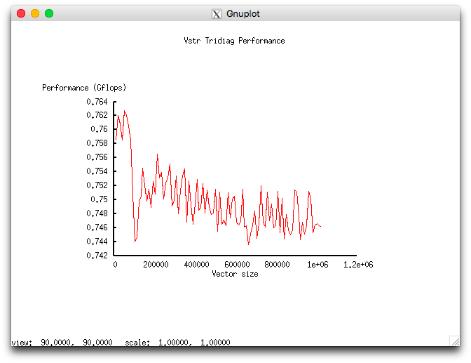
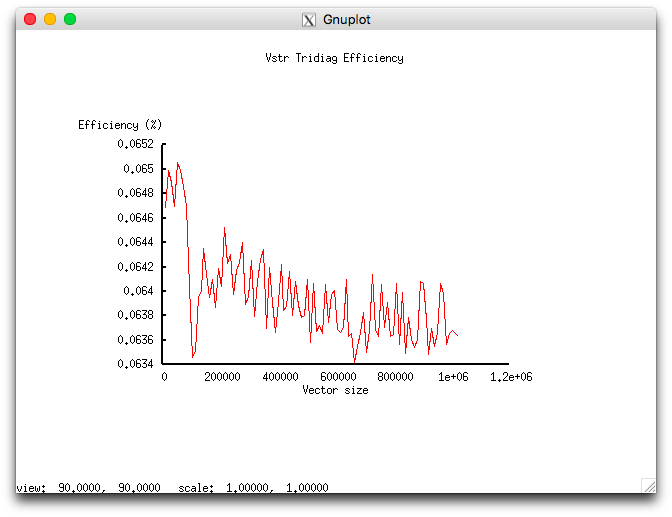
An analysis of scalability was performed for this algorithm as implemented in accordance with the methodology. The analysis was based on the experiments conducted on the Lomonosov supercomputer [5] of the Moscow University Supercomputing Center.
The variable start-up parameters of this implementation and their ranges are as follows:
- the number of processors is 1;
- the domain size varies in the range [10240 : 1024000] with the step 10240.
The experiments resulted in the following range for the implementation efficiency of this algorithm:
- the minimum efficiency is 0.0634%;
- the maximum efficiency is 0.0651%.
The following two figures show how the performance and efficiency of this implementation depend on the variable start-up parameters.
The meager efficiency is likely to be related to the excessive locality discussed in the section on the locality of data and calculations.
This analysis was performed for the algorithm implementation
2.5 Dynamic characteristics and efficiency of the algorithm implementation
In view of the serial nature of the algorithm and its excessive locality, the analysis of its dynamic characteristics seems to be of little value; therefore, it was not conducted.
2.6 Conclusions for different classes of computer architecture
The two-sided elimination method is intended for the classical von Neumann architecture. In order to parallelize the process of solving a SLAE with a tridiagonal coefficient matrix, one should use some parallel substitute of this method, for instance, the most popular cyclic reduction or the new serial-parallel method. The latter yields to the former in terms of the critical path of the graph, but, instead, its graph has a more regular structure.
2.7 Existing implementations of the algorithm
The two-sided elimination method is so simple that most of the users (researchers and application engineers) prefer to write their own program segments implementing this method (if they need it). Consequently, the method is ordinarily not included in program packages.
3 References
- ↑ V.V. Voevodin. Computational Foundations of Linear Algebra. Moscow, Nauka, 1977 (in Russian).
- ↑ V.V. Voevodin, Yu.A. Kuznetsov. Matrices and Computations. Moscow, Nauka, 1984 (in Russian).
- ↑ 3.0 3.1 A.A. Samarskii, E.S. Nikolaev. Numerical Methods for Grid Equations. Volume 1. Direct Methods. Birkhauser, 1989.
- ↑ A.V. Frolov, A.S. Antonov, Vl.V. Voevodin, A.M. Teplov. Comparison of different methods for solving the same problem on the basis of Algowiki methodology (in Russian) // Submitted to the conference "Parallel computational technologies" (PaVT'2016)"
- ↑ Vl. Voevodin, S. Zhumatii, S. Sobolev, A. Antonov, P. Bryzgalov, D. Nikitenko, K. Stefanov, Vad. Voevodin. Supercomputer "Lomonosov": Our Experience // Open Systems, 2012, N 7, P. 36-39 (in Russian)
