Difference between revisions of "Cholesky decomposition"
| [unchecked revision] | [unchecked revision] |
| Line 195: | Line 195: | ||
The most known is the compact packing of a graph: its projection onto the matrix triangle whose elements are recomputed by the packed operations. The «long» arcs can be eliminated and replaced by a combination of short-range arcs. | The most known is the compact packing of a graph: its projection onto the matrix triangle whose elements are recomputed by the packed operations. The «long» arcs can be eliminated and replaced by a combination of short-range arcs. | ||
| − | The following inequality is valid for the [[Glossary#equivalent perturbation| equivalent perturbation]] <math>M</math> of the Cholesky decomposition: | + | The following inequality is valid for the [[Glossary#equivalent perturbation| equivalent perturbation]] <math>M</math> of the Cholesky decomposition: |
<math> | <math> | ||
||M||_{E} \leq 2||\delta A||_{E}, | ||M||_{E} \leq 2||\delta A||_{E}, | ||
Revision as of 12:56, 23 February 2015
|
Properties of the algorithm:
|
Contents
- 1 Properties and structure of the algorithm
- 1.1 General description
- 1.2 Mathematical description
- 1.3 Computational kernel of the Cholesky algorithm
- 1.4 Macrostructure of the Cholesky algorithm
- 1.5 The implementation scheme of the sequential algorithm
- 1.6 Sequential complexity of the algorithm
- 1.7 Information graph
- 1.8 Parallelization resources of the algorithm
- 1.9 Input and output data of the algorithm
- 1.10 Properties of the algorithm
- 2 Software implementation
- 2.1 Implementation peculiarities of the sequential algorithm
- 2.2 Описание локальности данных и вычислений
- 2.3 Возможные способы и особенности реализации параллельного алгоритма
- 2.4 Масштабируемость алгоритма и его реализации
- 2.5 Динамические характеристики и эффективность реализации алгоритма
- 2.6 Выводы для классов архитектур
- 2.7 Существующие реализации алгоритма
- 3 Литература
1 Properties and structure of the algorithm
1.1 General description
The Cholesky decomposition algorithm was first proposed by Andre-Louis Cholesky (October 15, 1875 - August 31, 1918) at the end of the First World War shortly before he was killed in battle. He was a French military officer and mathematician. The idea of this algorithm was published in 1924 by his fellow officer and, later, was used by Banachiewicz in 1938 [7]. In the Russian mathematical literature, the Cholesky decomposition is also known as the square-root method [1-3] due to the square root operations used in this decomposition and not used in Gaussian elimination.
Originally, the Cholesky decomposition was used only for dense symmetric positive definite matrices. At present, the application of this decomposition is much wider. For example, it can also be employed for the case of Hermitian matrices. In order to increase the computing performance, its block versions are often applied.
In the case of sparse matrices, the Cholesky decomposition is also widely used as the main stage of a direct method for solving linear systems. In order to reduce the memory requirements and the profile of the matrix, special reordering strategies are applied to minimize the number of arithmetic operations. A number of reordering strategies are used to identify the independent matrix blocks for parallel computing systems.
Various versions of the Cholesky decomposition are successfully used in iterative methods to construct preconditioners for sparse symmetric positive definite matrices. In the case of incomplete triangular decomposition, the elements of a preconditioning matrix are specified only in predetermined positions (for example, in the positions of the nonzero elements; this version is known as the IC0 decomposition). In order to construct a more accurate decomposition, a filtration of small elements is performed using a filtration threshold. The use of such a threshold allows one to obtain an accurate decomposition, but the number of nonzero elements increases. A decomposition algorithm of second-order accuracy is discussed in [11]; this algorithm retains the number of nonzero elements in the factors of the decomposition and allows one to increase the accuracy. In its parallel implementation, a special version of an additive preconditioner is applied on the basis of the second-order decomposition [12].
Here we consider the original version of the Cholesky decomposition for dense real symmetric positive definite matrices. For a number of other versions, however, the structure of this decomposition is almost the same (for example, for the complex case): the distinctions consist in the change of most real operations by the corresponding complex operations. A list of other basic versions of the Cholesky decomposition is available on the page The Cholesky method (symmetric triangular decomposition).
For positive definite Hermitian matrices (symmetric matrices in the real case), we use the decomposition A = L L^*, where L is the lower triangular matrix, or the decomposition A = U^* U, where U is the upper triangular matrix. These forms of the Cholesky decomposition are equivalent in the sense of the amount of arithmetic operations and are different in the sense of data represntation. The essence of this decomposition consists in the implementation of formulas obtained uniquely for the elements of the matrix L form the above equality. The Cholesky decomposition is widely used due to the following features.
1.1.1 Symmetry of matrices
The symmetry of a matrix allows one to store in computer memory slightly more than half the number of its elements and to reduce the number of operations by a factor of two compared to Gaussian elimination. Note that the LU-decomposition does not require the square-root operations when using the property of symmetry and, hence, is somewhat faster than the Cholesky decomposition, but requires to store the entire matrix.
1.1.2 Accumulation mode
The Cholesky decomposition allows one to use the so-called accumulation mode due to the fact that the significant part of computation involves dot product operations. Hence, these dot products can be accumulated in double precision for additional accuracy. In this mode, the Cholesky method has the least equivalent perturbation. During the process of decomposition, no growth of the matrix elements can occur, since the matrix is symmetric and positive definite. Thus, the Cholesky algorithm is unconditionally stable.
1.2 Mathematical description
Input data: a symmetric positive definite matrix A whose elements are denoted by a_{ij}).
Output data: the lower triangular matrix L whose elements are denoted by l_{ij}).
The Cholesky algorithm can be represented in the form
- \begin{align} l_{11} & = \sqrt{a_{11}}, \\ l_{j1} & = \frac{a_{j1}}{l_{11}}, \quad j \in [2, n], \\ l_{ii} & = \sqrt{a_{ii} - \sum_{p = 1}^{i - 1} l_{ip}^2}, \quad i \in [2, n], \\ l_{ji} & = \left (a_{ji} - \sum_{p = 1}^{i - 1} l_{ip} l_{jp} \right ) / l_{ii}, \quad i \in [2, n - 1], j \in [i + 1, n]. \end{align}
There exist block versions of this algorithm; however, here we consider only its “dot” version.
In a number of implementations, the division by the diagonal element l_{ii} is made in the following two steps: the computation of \frac{1}{l_{ii}} and, then, the multiplication of the result by the modified values of a_{ji} . Here we do not consider this computational scheme, since this scheme has worse parallel characteristics than that given above.
1.3 Computational kernel of the Cholesky algorithm
A computational kernel of its sequential version can be composed of \frac{n (n - 1)}{2} dot products of the matrix rows:
- \sum_{p = 1}^{i - 1} l_{ip} l_{jp}.
These dot products can be accumulated in double precision for additional accuracy.
In many implementations, however, the operation
- a_{ji} - \sum_{p = 1}^{i - 1} l_{ip} l_{jp}
is performed by subtracting the componentwise products as parts of dot products from a_{ji} instead of subtracting the entire dot product from a_{ji}. Hence, the following operation should be considered as a computational kernel instead of the dot product operation:
- a_{ji} - \sum_{p = 1}^{i - 1} l_{ip} l_{jp}.
Here the accumulation in double precision can also be used.
The Cholesky algorithm is implemented in the LINPACK and LAPACK libraries on the basis of the BLAS library by using the SDOT dot product subprogram. In the sequential mode, this approach involves an additional sum operation for each of the elements of the matrix L (the total number of these elements is equal to \frac{n (n + 1)}{2}) and causes a certain slowing of the algorithm performance. Other consequences are discussed in the subsection «Existing implementations of the algorithm»). In the BLAS-based implementations, thus, the computational kernel of the Cholesky algorithm consists of dot products.
1.4 Macrostructure of the Cholesky algorithm
As shown above, the main part of the Cholesky algorithm consists of the following \frac{n (n - 1)}{2} operations (with or without accumulation):
- a_{ji}-\sum_{p=1}^{i-1}l_{ip} l_{jp}.
1.5 The implementation scheme of the sequential algorithm
This scheme can be represented as
1. l_{11}= \sqrt{a_{11}}
2. l_{j1}= \frac{a_{j1}}{l_{11}} (for j from 2 to n).
For all i from 2 to n:
3. l_{ii} = \sqrt{a_{ii} - \sum_{p = 1}^{i - 1} l_{ip}^2} and
4. (except for i = n): l_{ji} = \left (a_{ji} - \sum_{p = 1}^{i - 1} l_{ip} l_{jp} \right ) / l_{ii} (for all j from i + 1 to n).
If i \lt n, then i = i+1 and go to step 3.
In the above two formulas, the computation of a_{ji} - \sum_{p = 1}^{i - 1} l_{ip} l_{jp} can be performed in the accumulation mode: the sum is computed in double precision and is rounded off before the subtraction.
1.6 Sequential complexity of the algorithm
The following number of operations should be performed to decompose a matrix of order n using a sequential version of the Cholesky algorithm:
- n square roots,
- \frac{n(n-1)}{2} divisiona,
- по \frac{n^3-n}{6} multiplications and additions (subtractions) — the main amount of computational work.
In the accumulation mode, the multiplication and subtraction operations should be made in double precision (or by using the corresponding function, like the DPROD function in Fortran), which increases the overall computation time of the Cholesky algorithm.
Thus, a sequential version of the Cholesky algorithm is of cubic complexity.
1.7 Information graph
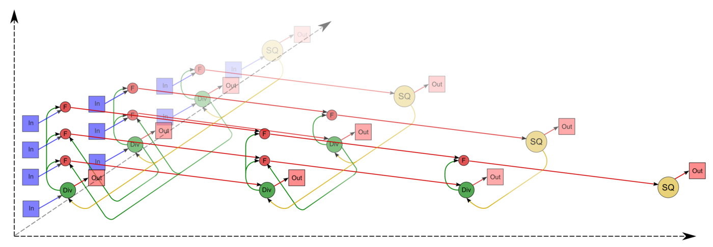
The graph of the algorithm consists of three groups of vertices positioned in the integer-valued nodes of three domains of different dimension.
The first group of vertices belongs to the one-dimensional domain corresponding to the SQRT operation. The only coordinate i of each vertex changes in the range from 1 to n and takes all integer values from this range.
Argument of this operation:
- for i = 1: the argument is a_{11};
- for i \gt 1: the argument is the result of the operation corresponding to the vertex of the third group with coordinates i - 1, i, i - 1.
The result of the SQRT operation is l_{ii}.
The second group of vertices belongs to the one-dimensional domain corresponding to the operation a / b. The coordinates of this domain are as follows:
- the coordinate i changes in the range from 1 to n-1 and takes all integer values from this range;
- the coordinate j changes in the range from i+1 to n and takes all integer values from this range.
Arguments of this operation:
- the numerator a:
- for i = 1: the element a_{j1};
- for i \gt 1: the result of the operation corresponding to the vertex of the third group with coordinates i - 1, j, i - 1;
- the denominator b: the result of the operation corresponding to the vertex of the first group with coordinate i.
The result of this operation is l_{ji}.
The third group of vertices belongs to the three-dimensional domain corresponding to the operation a - b * c. The coordinates of this domain are as follows:
- the coordinate i changes in the range from 2 to n and takes all integer values from this range;
- the coordinate j changes in the range from i to n and takes all integer values from this range;
- the coordinate p changes in the range from 1 to i - 1 and takes all integer values from this range.
Arguments of this operation:
- a:
- for p = 1: the element a_{ji};
- for p \gt 1: the result of the operation corresponding to the vertex of the third group with coordinates i, j, p - 1;
- b: the result of the operation corresponding to the vertex of the second group with coordinates p, i;
- c: the result of the operation corresponding to the vertex of the second group with coordinates p, j.
The result of this operation is intermediate for the Cholesky algorithm.
The above graph is illustrated in Figs. 1 and 2 for n = 4. In these figures, the vertices of the first group are marked yellow and by the letters sq; the vertices of the second group are marked green and by the division sign; the vertices of the third group are marked by red and by the letter f. The vertices corresponding to the results of operations (output data) are marked by larger circles. The arcs doubling one another are depicted as a single one. The representation of the graph shown in Fig. 1 corresponds to the classical definition. The graph of Fig. 2 contains additional vertices corresponding to input data (blue) and to output data (pink).
The following material is also available: graph of the Cholesky algorithm in the Sigma language.
1.8 Parallelization resources of the algorithm
In order to decompose a matrix of order n, a parallel version of the Cholesky algorithm should sequentially perform the following layers of operations:
- n layers for square roots (a single square root on each layer;
- n - 1 layers for divisions (on each of the layers, the number of divisions is linear and, depending on a particular layer, varies from 1 to n - 1);
- n - 1 layers of multiplications and n - 1 layers of addition/subtraction (on each of the layers, the number of these operations is quadratic and varies from 1 to \frac{n^2 - n}{2}).
Contrary to a sequential version, in a parallel version the square-root and division operations require a significant part of overall computational time. The existence of isolated square roots on some layers of the parallel form may cause other difficulties for particular parallel computing architectures. In the case of programmable logic devices (PLD), for example, the operations of division, multiplication and addition/subtraction can be conveyorized, which is efficient in resource saving for programmable boards, whereas the isolated square roots acquire resources of such boards and force them to be out of action for a significant period of time. In the case of symmetric linear systems, the Cholesky decomposition is preferable compared to Gaussian elimination because of the reduction in computational time by a factor of two. However, this is not true in the case of its parallel version.
In addition, we should mention the fact that the accumulation mode requires multiplications and subtraction in double precision. In a parallel version, this means that almost all intermediate computations should be performed with data given in their double precision format. Contrary to a sequential version, hence, this almost doubles the memory expenditures.
Thus, the Cholesky decomposition belongs to the class of algorithms of linear complexity in the sense of the height of its parallel form, whereas its complexity is quadratic in the sense of the width of its parallel form.
1.9 Input and output data of the algorithm
Input data: a dense matrix A of order n; its elements are denoted by a_{ij}. The additional conditions:
- A is a symmetric matrix (i.e., a_{ij}= a_{ji}, i, j = 1, \ldots, n).
- A is a positive definite matrix (i.e., \vec{x}^T A \vec{x} \gt 0 for any nonzero vector \vec{x} of length n.
Amount of input data: \frac{n (n + 1)}{2} ; since the matrix is symmetric, it is sufficient to store only its main diagonal and the elements above or under this diagonal. In practice, this storage saving scheme can be implemented in various ways. In the Numerical Analysis Library developed at the Moscow University Research Computing Center, for example, the lower triangle of the matrix A is stored row-wise in a one-dimensional array of length \frac{n (n + 1)}{2}.
Output data: the lower triangular matrix L whose elements are denoted by l_{ij}.
Amount of output data: \frac{n (n + 1)}{2} ; since the matrix L is lower triangular, it is sufficient to store only its main diagonal and the elements under this diagonal. In practice, this storage saving scheme can be implemented in various ways. In the above-mentioned library, for example, the matrix L is stored row-wise in a one-dimensional array of length \frac{n (n + 1)}{2}.
1.10 Properties of the algorithm
In the case of unlimited computer resources, the ratio of the sequential complexity to the parallel complexity is quadratic.
The computational power of the Cholesky algorithm considered as the ratio of the number of operations to the amount of input and output data is only linear.
The Cholesky is almost completely deterministic, which is ensured by the uniqueness theorem for this particular decomposition. Another order of associative operations may lead to the accumulation of round-off errors; however, the effect of this accumulation is not so large as in the case of not using the accumulation mode when computing dot products.
The information graph arcs from the vertices corresponding to the square-root and division operations can be considered as bundles of data such that the function relating the multiplicity of these vertices and the number of these operations is a linear function of the matrix order and the vertex coordinates. These bundles may contain «long» arcs; the remaining arcs are local.
The most known is the compact packing of a graph: its projection onto the matrix triangle whose elements are recomputed by the packed operations. The «long» arcs can be eliminated and replaced by a combination of short-range arcs.
The following inequality is valid for the equivalent perturbation M of the Cholesky decomposition: ||M||_{E} \leq 2||\delta A||_{E}, where \delta A is the perturbation of the matrix A caused by the representation of the matrix elements in the computer memory. Such a slow growth of matrix elements during decomposition is due to the fact that the matrix is symmetric and positive definite.
2 Software implementation
2.1 Implementation peculiarities of the sequential algorithm
В простейшем (без перестановок суммирования) варианте метод Холецкого на Фортране можно записать так:
	DO  I = 1, N
		S = A(I,I)
		DO  IP=1, I-1
			S = S - DPROD(A(I,P), A(I,IP))
		END DO
		A(I,I) = SQRT (S)
		DO  J = I+1, N
			S = A(J,I)
			DO  IP=1, I-1
				S = S - DPROD(A(I,P), A(J,IP))
			END DO
			A(J,I) = S/A(I,I)
		END DO
	END DO
При этом для реализации режима накопления переменная S должна быть двойной точности.
Для метода Холецкого существует блочная версия, которая отличается от точечной не тем, что операции над числами заменены на аналоги этих операций над блоками; её построение основано на том, что практически все циклы точечной версии имеют тип SchedDo в терминах методологии, основанной на исследовании информационного графа и, следовательно, могут быть расщеплены на составляющие. Тем не менее, обычно блочную версию метода Холецкого записывают не в виде программы с расщеплёнными и переставленными циклами, а в виде программы, подобной реализации точечного метода, в которой вместо соответствующих скалярных операций присутствуют операции над блоками.
Для обеспечения локальности работы с памятью представляется более эффективной такая схема метода Холецкого (полностью эквивалентная описанной), когда исходная матрица и её разложение хранятся не в нижнем-левом, а в правом-верхнем треугольнике. Это связано с особенностью размещения массивов в Фортране и тем, что в этом случае вычисления скалярных произведений будут идти с выборкой идущих подряд элементов массива.
Есть и другой вариант точечной схемы: использовать вычисляемые элементы матрицы L в качестве аргументов непосредственно «сразу после» их вычисления. Такая программа будет выглядеть так:
	DO  I = 1, N
		A(I,I) = SQRT (A(I, I))
		DO  J = I+1, N
			A(J,I) = A(J,I)/A(I,I)
		END DO
		DO  K=I+1,N
			DO J = K, N
				A(J,K) = A(J,K) - A(J,I)*A(K,I)
			END DO
		END DO
	END DO
Как видно, в этом варианте для реализации режима накопления одинарной точности мы должны будем объявить двойную точность для массива, хранящего исходные данные и результат. Подчеркнём, что граф алгоритма обеих схем - один и тот же (из п.1.7), если не считать изменением замену умножения на функцию DPROD!
2.2 Описание локальности данных и вычислений
2.2.1 Описание локальности алгоритма
2.2.2 Описание локальности реализации алгоритма
2.2.2.1 Описание структуры обращений в память и качественная оценка локальности
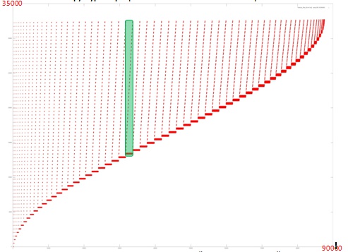
На рисунке 1 представлен профиль обращений в память для реализации метода Холецкого. В программе задействован только 1 массив, поэтому в данном случае обращения в профиле происходят только к элементам этого массива. Программа состоит из одного основного этапа, который, в свою очередь, состоит из последовательности подобных итераций. Пример одной итерации выделен зеленым цветом.
Видно, что на каждой i-й итерации используются все адреса, кроме первых k_i, при этом с ростом i увеличивается значение k_i. Также можно заметить, что число обращений в память на каждой итерации растет примерно до середины работы программы, после чего уменьшается вплоть до завершения работы. Это позволяет говорить о том, что данные в программе используются неравномерно, при этом многие итерации, особенно в начале выполнения программы, задействуют большой объем данных, что приводит к ухудшению локальности.
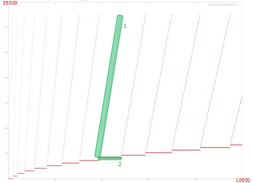
Однако в данном случае основным фактором, влияющим на локальность работы с памятью, является строение итерации. Рассмотрим фрагмент профиля, соответствующий нескольким первым итерациям.
Исходя из рисунка 2 видно, что каждая итерация состоит из двух различных фрагментов. Фрагмент 1 – последовательный перебор (с некоторым шагом) всех адресов, начиная с некоторого начального. При этом к каждому элементу происходит мало обращений. Такой фрагмент обладает достаточно неплохой пространственной локальностью, так как шаг по памяти между соседними обращениями невелик, но плохой временно́й локальностью, поскольку данные редко используются повторно.
Фрагмент 2 устроен гораздо лучше с точки зрения локальности. В рамках этого фрагмента выполняется большое число обращений подряд к одним и тем же данным, что обеспечивает гораздо более высокую степень как пространственной, так и временно́й локальности по сравнению с фрагментом 1.
После рассмотрения фрагмента профиля на рис. 2 можно оценить общую локальность двух фрагментов на каждой итерации. Однако стоит рассмотреть более подробно, как устроен каждый из фрагментов.
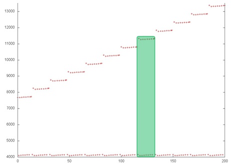
Рис. 3, на котором представлена часть одной итерации общего профиля, позволяет отметить достаточно интересный факт: строение каждого из фрагментов на самом деле заметно сложнее, чем это выглядит на рис. 2. В частности, каждый шаг фрагмента 1 состоит из нескольких обращений к соседним элементам, причем выполняется не последовательный перебор. Также можно увидеть, что фрагмент 2 на самом деле в свою очередь состоит из повторяющихся итераций, при этом видно, что каждый шаг фрагмента 1 соответствует одной итерации фрагмента 2 (выделено зеленым на рис. 3). Это лишний раз говорит о том, что для точного понимания локальной структуры профиля необходимо его рассмотреть на уровне отдельных обращений.
Стоит отметить, что выводы на основе рис. 3 просто дополняют общее представлении о строении профиля обращений; сделанные на основе рис. 2 выводы относительно общей локальности двух фрагментов остаются верны.
2.2.2.2 Количественная оценка локальности
Основной фрагмент реализации, на основе которого были получены количественные оценки, приведен здесь (функция Kernel). Условия запуска описаны здесь.
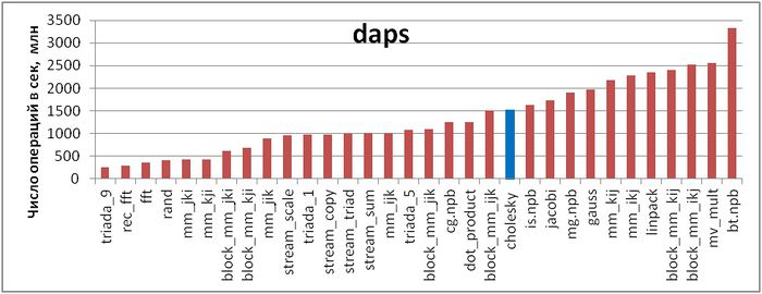
Первая оценка выполняется на основе характеристики daps, которая оценивает число выполненных обращений (чтений и записей) в память в секунду. Данная характеристика является аналогом оценки flops применительно к работе с памятью и является в большей степени оценкой производительности взаимодействия с памятью, чем оценкой локальности. Однако она служит хорошим источником информации, в том числе для сравнения с результатами по следующей характеристике cvg.
На рисунке 4 приведены значения daps для реализаций распространенных алгоритмов, отсортированные по возрастанию (чем больше daps, тем в общем случае выше производительность). Можно увидеть, что реализация метода Холецкого характеризуется достаточно высокой скоростью взаимодействия с памятью, однако ниже, чем, например, у теста Линпак или реализации метода Якоби.
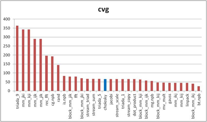
Вторая характеристика – cvg – предназначена для получения более машинно-независимой оценки локальности. Она определяет, насколько часто в программе необходимо подтягивать данные в кэш-память. Соответственно, чем меньше значение cvg, тем реже это нужно делать, тем лучше локальность.
На рисунке 5 приведены значения cvg для того же набора реализаций, отсортированные по убыванию (чем меньше cvg, тем в общем случае выше локальность). Можно увидеть, что, согласно данной оценке, реализация метода Холецкого оказалась ниже в списке по сравнению с оценкой daps.
2.3 Возможные способы и особенности реализации параллельного алгоритма
Как нетрудно видеть по структуре графа алгоритма, вариантов распараллеливания алгоритма довольно много. Например, во втором варианте (см. раздел «Особенности реализации последовательного алгоритма») все внутренние циклы параллельны, в первом — параллелен цикл по J. Тем не менее, простое распараллеливание таким способом «в лоб» вызовет такое количество пересылок между процессорами с каждым шагом по внешнему циклу, которое почти сопоставимо с количеством арифметических операций. Поэтому перед размещением операций и данных между процессорами вычислительной системы предпочтительно разбиение всего пространства вычислений на блоки, с сопутствующим разбиением обрабатываемого массива.
Многое зависит от конкретного типа вычислительной системы. Присутствие конвейеров на узлах многопроцессорной системы делает рентабельным параллельное вычисление нескольких скалярных произведений сразу. Подобная возможность есть и на программировании ПЛИСов, но там быстродействие будет ограничено медленным последовательным выполнением операции извлечения квадратного корня.
В принципе, возможно и использование т. н. «скошенного» параллелизма. Однако его на практике никто не использует, из-за усложнения управляющей структуры программы.
2.4 Масштабируемость алгоритма и его реализации
2.4.1 Описание масштабируемости алгоритма
2.4.2 Описание масштабируемости реализации алгоритма
Проведём исследование масштабируемости параллельной реализации разложения Холецкого согласно методике. Исследование проводилось на суперкомпьютере "Ломоносов" Суперкомпьютерного комплекса Московского университета.
Набор и границы значений изменяемых параметров запуска реализации алгоритма:
- число процессоров [4 : 256] с шагом 4;
- размер матрицы [1024 : 5120].
В результате проведённых экспериментов был получен следующий диапазон эффективности реализации алгоритма:
- минимальная эффективность реализации 0,11%;
- максимальная эффективность реализации 2,65%.
На следующих рисунках приведены графики производительности и эффективности выбранной реализации разложения Холецкого в зависимости от изменяемых параметров запуска.
Построим оценки масштабируемости выбранной реализации разложения Холецкого:
- По числу процессов: -0,000593. При увеличении числа процессов эффективность на рассмотренной области изменений параметров запуска уменьшается, однако в целом уменьшение не очень быстрое. Малая интенсивность изменения объясняется крайне низкой общей эффективностью работы приложения с максимумом в 2,65%, и значение эффективности на рассмотренной области значений быстро доходит до десятых долей процента. Это свидетельствует о том, что на большей части области значений нет интенсивного снижения эффективности. Это объясняется также тем, что с ростом вычислительной сложности падение эффективности становится не таким быстрым. Уменьшение эффективности на рассмотренной области работы параллельной программы объясняется быстрым ростом накладных расходов на организацию параллельного выполнения. С ростом вычислительной сложности задачи эффективность снижается так же быстро, но при больших значениях числа процессов. Это подтверждает предположение о том, что накладные расходы начинают сильно превалировать над вычислениями.
- По размеру задачи: 0,06017. При увеличении размера задачи эффективность возрастает. Эффективность возрастает тем быстрее, чем большее число процессов используется для выполнения. Это подтверждает предположение о том, что размер задачи сильно влияет на эффективность выполнения приложения. Оценка показывает, что с ростом размера задачи эффективность на рассмотренной области значений параметров запуска сильно увеличивается. Также, учитывая разницу максимальной и минимальной эффективности в 2,5%, можно сделать вывод, что рост эффективности при увеличении размера задачи наблюдается на большей части рассмотренной области значений.
- По двум направлениям: 0,000403. При рассмотрении увеличения как вычислительной сложности, так и числа процессов на всей рассмотренной области значений эффективность увеличивается, однако скорость увеличения эффективности небольшая. В совокупности с тем фактом, что разница между максимальной и минимальной эффективностью на рассмотренной области значений параметров небольшая, эффективность с увеличением масштабов возрастает, но медленно и с небольшими перепадами.
Исследованная параллельная реализация на языке C
2.5 Динамические характеристики и эффективность реализации алгоритма
Для существующих параллельных реализаций характерно отнесение всего ресурса параллелизма на блочный уровень. Относительно низкая эффективность работы связана с проблемами внутри одного узла, следующим фактором является неоптимальное соотношение между «арифметикой» и обменами. Видно, что при некотором (довольно большом) оптимальном размере блока обмены влияют не так уж сильно.
Для проведения экспериментов использовалась реализация разложения Холецкого, представленная в пакете SCALAPACK библиотеки Intel MKL (метод pdpotrf). Все результаты получены на суперкомпьютере «Ломоносов». Использовались процессоры Intel Xeon X5570 с пиковой производительностью в 94 Гфлопс, а также компилятор Intel с опцией –O2.
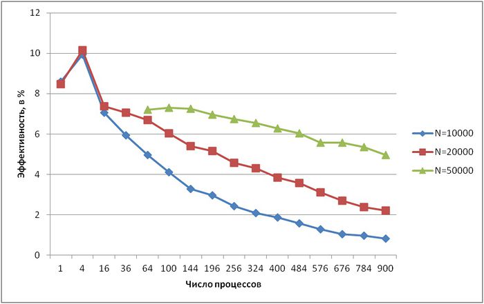
На рисунке показана эффективность реализации разложения Холецкого (случай использования нижних треугольников матриц) для разного числа процессов и разной размерности матрицы (10000, 20000 и 50000 элементов). Видно, что общая эффективность достаточно невысока – даже при малом числе процессов менее 10 %. Однако при всех размерностях матрицы эффективность снижается очень медленно – в самом худшем случае, при N = 10000, при увеличении числа процессов с 16 до 900 (в 56 раз) эффективность падает с 7 % до 0,8 % (всего в 9 раз). При N = 50000 эффективность уменьшается еще медленнее.
Также стоит отметить небольшое суперлинейное ускорение, полученное на 4-х процессах для N = 10000 и N = 20000 (для N = 50000 провести эксперименты на таком малом числе процессов не удалось). Помимо более эффективной работы с кэш-памятью, оно, видимо, обусловлено тем, что эти 4 процесса помещаются на ядрах одного процессора, что позволяет использовать общую память, и, соответственно, не приводит к появлению накладных расходов, связанных с пересылкой данных.
2.6 Выводы для классов архитектур
Как видно по показателям SCALAPACK на суперкомпьютерах, обмены при большом n хоть и уменьшают эффективность расчётов, но слабее, чем неоптимальность организации расчётов внутри одного узла. Поэтому, видимо, следует сначала оптимизировать не блочный алгоритм, а подпрограммы, используемые на отдельных процессорах: точечный метод Холецкого, перемножения матриц и др. подпрограммы. Ниже содержится информация о возможном направлении такой оптимизации.
В отношении же архитектуры типа ПЛИС вполне показателен тот момент, что разработчики — наполнители библиотек для ПЛИСов пока что не докладывают об успешных и эффективных реализациях точечного метода Холецкого на ПЛИСах. Это связано со следующим свойством информационной структуры алгоритма: если операции деления или вычисления выражений a - bc являются не только массовыми, но и параллельными, и потому их вычисления сравнительно легко выстраивать в конвейеры, то операции извлечения квадратных корней являются узким местом алгоритма - отведённое на эту операцию оборудование неизбежно будет простаивать большую часть времени. Поэтому для эффективной реализации на ПЛИСах алгоритмов, столь же хороших по вычислительным характеристикам, как и метод квадратного корня, следует использовать не метод Холецкого, а его давно известную модификацию без извлечения квадратных корней — разложение матрицы в произведение L D L^T.
2.7 Существующие реализации алгоритма
Точечный метод Холецкого реализован как в основных библиотеках программ отечественных организаций, так и в западных пакетах LINPACK, LAPACK, SCALAPACK и др.
При этом в отечественных реализациях, как правило, выполнены стандартные требования к методу с точки зрения ошибок округления, то есть, реализован режим накопления, и обычно нет лишних операций. Правда, анахронизмом в наше время выглядит то, что ряд старых отечественных реализаций использует для экономии памяти упаковку матриц A и L в одномерный массив. При реальных вычислениях на современных вычислительных системах данная упаковка только создаёт дополнительные накладные расходы. Однако отечественные реализации, не использующие такую упаковку, вполне отвечают требованиям современности в отношении вычислительной точности метода.
Реализация точечного метода Холецкого в современных западных пакетах страдает другими недостатками, вытекающими из того, что все эти реализации, по сути, происходят из одной и той же реализации метода в LINPACK, а та использует пакет BLAS. Основным их недостатком является даже не наличие лишних операций, о котором уже написано в разделе «Вычислительное ядро алгоритма», ибо их количество всё же невелико по сравнению с главной частью, а то, что в BLAS скалярное произведение реализовано без режима накопления. Это перечёркивает имеющиеся для метода Холецкого хорошие оценки влияния ошибок округления, поскольку они выведены как раз в предположении использования режима накопления при вычислении скалярных произведений. Поэтому тот, кто использует реализации метода Холецкого из LINPACK, LAPACK, SCALAPACK и т. п. пакетов, серьёзно рискует не получить требуемую вычислительную точность, либо ему придётся для получения хороших оценок одинарной точности использовать подпрограммы двойной.
В крупнейших библиотеках алгоритмов до сих пор предлагается именно разложение Холецкого, а более быстрый алгоритм LU-разложения без извлечения квадратных корней используется только в особых случаях (например, для трёхдиагональных матриц), в которых количество диагональных элементов уже сравнимо с количеством внедиагональных.
3 Литература
- Воеводин В.В. Вычислительные основы линейной алгебры. М.: Наука, 1977.
- Воеводин В.В., Кузнецов Ю.А. Матрицы и вычисления. М.: Наука, 1984.
- Фаддеев Д.К., Фаддева В.Н. Вычислительные основы линейной алгебры. М.-Л.: Физматгиз, 1963.
- Воеводин В.В. Математические основы параллельных вычислений// М.: Изд. Моск. ун-та, 1991. 345 с.
- Фролов А.В.. Принципы построения и описание языка Сигма. Препринт ОВМ АН N 236. М.: ОВМ АН СССР, 1989.
- Commandant Benoit, Note sur une méthode de résolution des équations normales provenant de l'application de la méthode des moindres carrés à un système d'équations linéaires en nombre inférieur à celui des inconnues (Procédé du Commandant Cholesky), Bulletin Géodésique 2 (1924), 67-77.
- Banachiewicz T. Principles d'une nouvelle technique de la méthode des moindres carrês. Bull. Intern. Acad. Polon. Sci. A., 1938, 134-135.
- Banachiewicz T. Méthode de résoltution numérique des équations linéaires, du calcul des déterminants et des inverses et de réduction des formes quardatiques. Bull. Intern. Acad. Polon. Sci. A., 1938, 393-401.
- Krishnamoorthy A., Menon D. Matrix Inversion Using Cholesky Decomposition. 2013. eprint arXiv:1111.4144
- Открытая энциклопедия свойств алгоритмов. URL: http://algowiki-project.org
- Kaporin I.E. High quality preconditioning of a general symmetric positive definite matrix based on its UTU + UTR + RTU-decomposition. Numer. Lin. Algebra Appl. (1998) Vol. 5, No. 6, 483-509.
- Капорин И.Е., Коньшин И.Н. Параллельное решение симметричных положительно-определенных систем на основе перекрывающегося разбиения на блоки. Ж. вычисл. матем. и матем. физ., 2001, Т, 41, N. 4, C. 515–528.
- Воеводин Вл., Жуматий С., Соболев С., Антонов А., Брызгалов П., Никитенко Д., Стефанов К., Воеводин Вад. Практика суперкомпьютера «Ломоносов» // Открытые системы, 2012, N 7, С. 36-39.
- Воеводин В.В., Воеводин Вл.В. Параллельные вычисления. – СПб.: БХВ - Петербург, 2002. – 608 с.
- Воеводин Вад. В. Визуализация и анализ профиля обращений в память // Вестник Южно-Уральского государственного университета. Серия Математическое моделирование и про-граммирование. — 2011. — Т. 17, № 234. — С. 76–84.
- Воеводин Вл. В., Воеводин Вад. В. Спасительная локальность суперкомпьютеров // Откры-тые системы. — 2013. — № 9. — С. 12–15.

