Cholesky decomposition
| Cholesky decomposition | |
| Sequential algorithm | |
| Serial complexity | [math]O(n^3)[/math] |
| Input data | [math]\frac{n (n + 1)}{2}[/math] |
| Output data | [math]\frac{n (n + 1)}{2}[/math] |
| Parallel algorithm | |
| Parallel form height | [math]O(n)[/math] |
| Parallel form width | [math]O(n^2)[/math] |
Main authors: Alexey Frolov, Vadim Voevodin (Section 2.2), Alexey Teplov (Sections 2.4, 2.5)
Contents
- 1 Properties and structure of the algorithm
- 1.1 General description of the algorithm
- 1.2 Mathematical description of the algorithm
- 1.3 Computational kernel of the algorithm
- 1.4 Macro structure of the algorithm
- 1.5 Implementation scheme of the serial algorithm
- 1.6 Serial complexity of the algorithm
- 1.7 Information graph
- 1.8 Parallelization resource of the algorithm
- 1.9 Input and output data of the algorithm
- 1.10 Properties of the algorithm
- 2 Software implementation of the algorithm
- 2.1 Implementation peculiarities of the serial algorithm
- 2.2 Locality of data and computations
- 2.3 Possible methods and considerations for parallel implementation of the algorithm
- 2.4 Scalability of the algorithm and its implementations
- 2.5 Dynamic characteristics and efficiency of the algorithm implementation
- 2.6 Conclusions for different classes of computer architecture
- 2.7 Existing implementations of the algorithm
- 3 References
1 Properties and structure of the algorithm
1.1 General description of the algorithm
The Cholesky decomposition algorithm was first proposed by Andre-Louis Cholesky (October 15, 1875 - August 31, 1918) at the end of the First World War shortly before he was killed in battle. He was a French military officer and mathematician. The idea of this algorithm was published in 1924 by his fellow officer[1] and, later, was used by Banachiewicz in 1938[2][3]. In the Russian mathematical literature, the Cholesky decomposition is also known as the square-root method[4][5][6] due to the square root operations used in this decomposition and not used in Gaussian elimination.
Originally, the Cholesky decomposition was used only for dense real symmetric positive definite matrices. At present, the application of this decomposition is much wider. For example, it can also be employed for the case of Hermitian matrices. In order to increase the computing performance, its block versions are often applied.
In the case of sparse matrices, the Cholesky decomposition is also widely used as the main stage of a direct method for solving linear systems. In order to reduce the memory requirements and the profile of the matrix, special reordering strategies are applied to minimize the number of arithmetic operations. A number of reordering strategies are used to identify the independent matrix blocks for parallel computing systems.
Various versions of the Cholesky decomposition are successfully used in iterative methods to construct preconditioners for sparse symmetric positive definite matrices. In the case of incomplete triangular decomposition, the elements of a preconditioning matrix are specified only in predetermined positions (for example, in the positions of the nonzero elements; this version is known as the IC0 decomposition). In order to construct a more accurate decomposition, a filtration of small elements is performed using a filtration threshold. The use of such a threshold allows one to obtain an accurate decomposition, but the number of nonzero elements increases. A decomposition algorithm of second-order accuracy is discussed in[7]; this algorithm retains the number of nonzero elements in the factors of the decomposition and allows one to increase the accuracy. In its parallel implementation, a special version of an additive preconditioner is applied on the basis of the second-order decomposition[8].
Here we consider the original version of the Cholesky decomposition for dense real symmetric positive definite matrices. For a number of other versions, however, the structure of this decomposition is almost the same (for example, for the complex case): the distinction consists in the change of the majority of real operations by the corresponding complex operations. A list of other basic versions of the Cholesky decomposition is available on the page Cholesky method.
For positive definite Hermitian matrices (symmetric matrices in the real case), we use the decomposition [math]A = L L^*[/math], where [math]L[/math] is the lower triangular matrix, or the decomposition [math]A = U^* U[/math], where [math]U[/math] is the upper triangular matrix. These forms of the Cholesky decomposition are equivalent in the sense of the amount of arithmetic operations and are different in the sense of data represntation. The essence of this decomposition consists in the implementation of formulas obtained uniquely for the elements of the matrix [math]L[/math] from the above equality. The Cholesky decomposition is widely used due to the following features.
1.1.1 Symmetry of matrices
The symmetry of a matrix allows one to store in computer memory slightly more than half the number of its elements and to reduce the number of operations by a factor of two compared to Gaussian elimination. Note that the LU-decomposition does not require the square-root operations when using the property of symmetry and, hence, is somewhat faster than the Cholesky decomposition, but requires to store the entire matrix.
1.1.2 Accumulation mode
The Cholesky decomposition allows one to use the so-called accumulation mode due to the fact that the significant part of computation involves dot product operations. Hence, these dot products can be accumulated in double precision for additional accuracy. In this mode, the Cholesky method has the least equivalent perturbation. During the process of decomposition, no growth of the matrix elements can occur, since the matrix is symmetric and positive definite. Thus, the Cholesky algorithm is unconditionally stable.
1.2 Mathematical description of the algorithm
Input data: a symmetric positive definite matrix [math]A[/math] whose elements are denoted by [math]a_{ij}[/math]).
Output data: the lower triangular matrix [math]L[/math] whose elements are denoted by [math]l_{ij}[/math]).
The Cholesky algorithm can be represented in the form
- [math] \begin{align} l_{11} & = \sqrt{a_{11}}, \\ l_{j1} & = \frac{a_{j1}}{l_{11}}, \quad j \in [2, n], \\ l_{ii} & = \sqrt{a_{ii} - \sum_{p = 1}^{i - 1} l_{ip}^2}, \quad i \in [2, n], \\ l_{ji} & = \left (a_{ji} - \sum_{p = 1}^{i - 1} l_{ip} l_{jp} \right ) / l_{ii}, \quad i \in [2, n - 1], j \in [i + 1, n]. \end{align} [/math]
There exist block versions of this algorithm; however, here we consider only its “dot” version.
In a number of implementations, the division by the diagonal element [math]l_{ii}[/math] is made in the following two steps: the computation of [math]\frac{1}{l_{ii}}[/math] and, then, the multiplication of the result by the modified values of [math]a_{ji}[/math] . Here we do not consider this computational scheme, since this scheme has worse parallel characteristics than that given above.
1.3 Computational kernel of the algorithm
A computational kernel of its serial version can be composed of [math]\frac{n (n - 1)}{2}[/math] dot products of the matrix rows:
- [math]\sum_{p = 1}^{i - 1} l_{ip} l_{jp}.[/math]
These dot products can be accumulated in double precision for additional accuracy.
In many implementations, however, the operation
- [math]a_{ji} - \sum_{p = 1}^{i - 1} l_{ip} l_{jp}[/math]
is performed by subtracting the componentwise products as parts of dot products from [math]a_{ji}[/math] instead of subtracting the entire dot product from [math]a_{ji}[/math]. Hence, the following operation should be considered as a computational kernel instead of the dot product operation:
- [math]a_{ji} - \sum_{p = 1}^{i - 1} l_{ip} l_{jp}[/math].
Here the accumulation in double precision can also be used.
The Cholesky algorithm is implemented in the LINPACK and LAPACK libraries on the basis of the BLAS library by using the SDOT dot product subprogram. In the serial mode, this approach involves an additional sum operation for each of the elements of the matrix [math]L[/math] (the total number of these elements is equal to [math]\frac{n (n + 1)}{2}[/math]) and causes a certain slowing of the algorithm performance. Other consequences are discussed in the subsection «Existing implementations of the algorithm»). In the BLAS-based implementations, thus, the computational kernel of the Cholesky algorithm consists of dot products.
1.4 Macro structure of the algorithm
As shown above, the main part of the Cholesky algorithm consists of the following [math]\frac{n (n - 1)}{2}[/math] operations (with or without accumulation):
- [math]a_{ji}-\sum_{p=1}^{i-1}l_{ip} l_{jp}[/math].
1.5 Implementation scheme of the serial algorithm
This scheme can be represented as
1. [math]l_{11}= \sqrt{a_{11}}[/math]
2. [math]l_{j1}= \frac{a_{j1}}{l_{11}}[/math] (for [math]j[/math] from [math]2[/math] to [math]n[/math]).
For all [math]i[/math] from [math]2[/math] to [math]n[/math]:
3. [math]l_{ii} = \sqrt{a_{ii} - \sum_{p = 1}^{i - 1} l_{ip}^2}[/math] and
4. (except for [math]i = n[/math]): [math]l_{ji} = \left (a_{ji} - \sum_{p = 1}^{i - 1} l_{ip} l_{jp} \right ) / l_{ii}[/math] (for all [math]j[/math] from [math]i + 1[/math] to [math]n[/math]).
If [math]i \lt n[/math], then [math]i = i+1[/math] and go to step 3.
In the above two formulas, the computation of [math]a_{ji} - \sum_{p = 1}^{i - 1} l_{ip} l_{jp}[/math] can be performed in the accumulation mode: the sum is computed in double precision and is rounded off before the subtraction.
1.6 Serial complexity of the algorithm
The following number of operations should be performed to decompose a matrix of order [math]n[/math] using a serial version of the Cholesky algorithm:
- [math]n[/math] square roots,
- [math]\frac{n(n-1)}{2}[/math] divisiona,
- [math]\frac{n^3-n}{6}[/math] multiplications and [math]\frac{n^3-n}{6}[/math] additions (subtractions): the main amount of computational work.
In the accumulation mode, the multiplication and subtraction operations should be made in double precision (or by using the corresponding function, like the DPROD function in Fortran), which increases the overall computation time of the Cholesky algorithm.
Thus, a serial version of the Cholesky algorithm is of cubic complexity.
1.7 Information graph
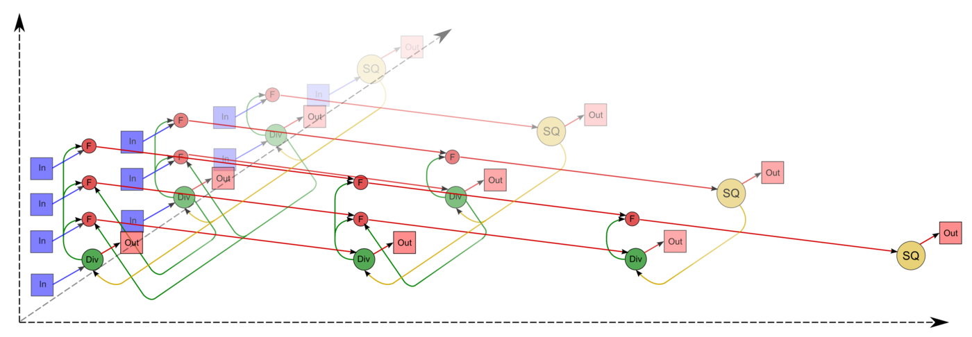
The graph of the algorithm[9][10][11] consists of three groups of vertices positioned in the integer-valued nodes of three domains of different dimension.
The first group of vertices belongs to the one-dimensional domain corresponding to the SQRT operation. The only coordinate [math]i[/math] of each vertex changes in the range from [math]1[/math] to [math]n[/math] and takes all integer values from this range.
Argument of this operation:
- for [math]i = 1[/math]: the argument is [math]a_{11}[/math];
- for [math]i \gt 1[/math]: the argument is the result of the operation corresponding to the vertex of the third group with coordinates [math]i - 1[/math], [math]i[/math], [math]i - 1[/math].
The result of the SQRT operation is [math]l_{ii}[/math].
The second group of vertices belongs to the one-dimensional domain corresponding to the operation [math]a / b[/math]. The coordinates of this domain are as follows:
- the coordinate [math]i[/math] changes in the range from [math]1[/math] to [math]n-1[/math] and takes all integer values from this range;
- the coordinate [math]j[/math] changes in the range from [math]i+1[/math] to [math]n[/math] and takes all integer values from this range.
Arguments of this operation:
- the numerator [math]a[/math]:
- for [math]i = 1[/math]: the element [math]a_{j1}[/math];
- for [math]i \gt 1[/math]: the result of the operation corresponding to the vertex of the third group with coordinates [math]i - 1, j, i - 1[/math];
- the denominator [math]b[/math]: the result of the operation corresponding to the vertex of the first group with coordinate [math]i[/math].
The result of this operation is [math]l_{ji}[/math].
The third group of vertices belongs to the three-dimensional domain corresponding to the operation [math]a - b * c[/math]. The coordinates of this domain are as follows:
- the coordinate [math]i[/math] changes in the range from [math]2[/math] to [math]n[/math] and takes all integer values from this range;
- the coordinate [math]j[/math] changes in the range from [math]i[/math] to [math]n[/math] and takes all integer values from this range;
- the coordinate [math]p[/math] changes in the range from [math]1[/math] to [math]i - 1[/math] and takes all integer values from this range.
Arguments of this operation:
- [math]a[/math]:
- for [math]p = 1[/math]: the element [math]a_{ji}[/math];
- for [math]p \gt 1[/math]: the result of the operation corresponding to the vertex of the third group with coordinates [math]i, j, p - 1[/math];
- [math]b[/math]: the result of the operation corresponding to the vertex of the second group with coordinates [math]p, i[/math];
- [math]c[/math]: the result of the operation corresponding to the vertex of the second group with coordinates [math]p, j[/math].
The result of this operation is intermediate for the Cholesky algorithm.
The above graph is illustrated in Figs. 1 and 2 for [math]n = 4[/math]. In these figures, the vertices of the first group are highlighted in yellow and are marked by the letters SQ; the vertices of the second group are highlighted in green and are marked by the division sign; the vertices of the third group are highlighted in red and are marked by the letter F. The vertices corresponding to the results of operations (output data) are marked by large circles. The arcs doubling one another are depicted as a single one. The representation of the graph shown in Fig.1 corresponds to the classical definition. The graph of Fig.2 contains additional vertices corresponding to input data (blue) and to output data (pink).
1.8 Parallelization resource of the algorithm
In order to decompose a matrix of order [math]n[/math], a parallel version of the Cholesky algorithm should serially perform the following layers of operations:
- [math]n[/math] layers for square roots (a single square root on each layer);
- [math]n - 1[/math] layers for divisions (on each of the layers, the number of divisions is linear and, depending on a particular layer, varies from [math]1[/math] to [math]n - 1[/math]);
- [math]n - 1[/math] layers of multiplications and [math]n - 1[/math] layers of addition/subtraction (on each of the layers, the number of these operations is quadratic and varies from [math]1[/math] to [math]\frac{n^2 - n}{2}[/math]).
Contrary to a serial version, in a parallel version the square-root and division operations require a significant part of overall computational time. The existence of isolated square roots on some layers of the parallel form may cause other difficulties for particular parallel computing architectures. In the case of programmable logic devices (PLD), for example, the operations of division, multiplication and addition/subtraction can be conveyorized, which is efficient in resource saving for programmable boards, whereas the isolated square roots acquire resources of such boards and force them to be out of action for a significant period of time. In the case of symmetric linear systems, the Cholesky decomposition is preferable compared to Gaussian elimination because of the reduction in computational time by a factor of two. However, this is not true in the case of its parallel version.
In addition, we should mention the fact that the accumulation mode requires multiplications and subtraction in double precision. In a parallel version, this means that almost all intermediate computations should be performed with data given in their double precision format. Contrary to a serial version, hence, this almost doubles the memory expenditure.
Thus, the Cholesky decomposition belongs to the class of algorithms of linear complexity in the sense of the height of its parallel form, whereas its complexity is quadratic in the sense of the width of its parallel form.
1.9 Input and output data of the algorithm
Input data: a dense matrix [math]A[/math] of order [math]n[/math]; its elements are denoted by [math]a_{ij}[/math]. The additional conditions:
- [math]A[/math] is a symmetric matrix (i.e., [math]a_{ij}= a_{ji}, i, j = 1, \ldots, n[/math]).
- [math]A[/math] is a positive definite matrix (i.e., [math]\vec{x}^T A \vec{x} \gt 0[/math] for any nonzero vector [math]\vec{x}[/math] of length [math]n[/math].
Amount of input data: [math]\frac{n (n + 1)}{2}[/math] ; since the matrix is symmetric, it is sufficient to store only its main diagonal and the elements above or under this diagonal. In practice, this storage saving scheme can be implemented in various ways. In the Numerical Analysis Library developed at the Moscow University Research Computing Center, for example, the lower triangle of the matrix [math]A[/math] is stored row-wise in a one-dimensional array of length [math]\frac{n (n + 1)}{2}[/math].
Output data: the lower triangular matrix [math]L[/math] whose elements are denoted by [math]l_{ij}[/math].
Amount of output data: [math]\frac{n (n + 1)}{2}[/math] ; since the matrix [math]L[/math] is lower triangular, it is sufficient to store only its main diagonal and the elements under this diagonal. In practice, this storage saving scheme can be implemented in various ways. In the above-mentioned library, for example, the matrix [math]L[/math] is stored row-wise in a one-dimensional array of length [math]\frac{n (n + 1)}{2}[/math].
1.10 Properties of the algorithm
In the case of unlimited computer resources, the ratio of the serial complexity to the parallel complexity is quadratic.
The computational power of the Cholesky algorithm considered as the ratio of the number of operations to the amount of input and output data is only linear.
The Cholesky is almost completely deterministic, which is ensured by the uniqueness theorem for this particular decomposition. Another order of associative operations may lead to the accumulation of round-off errors; however, the effect of this accumulation is not so large as in the case of not using the accumulation mode when computing dot products.
The information graph arcs from the vertices corresponding to the square-root and division operations can be considered as groups of data such that the function relating the multiplicity of these vertices and the number of these operations is a linear function of the matrix order and the vertex coordinates. These groups may contain «long» arcs; the remaining arcs are local.
The most known is the compact packing of a graph in the form of its projection onto the matrix triangle whose elements are recomputed by the packed operations. The «long» arcs can be eliminated and replaced by a combination of short-range arcs.
The following inequality is valid for the equivalent perturbation [math]M[/math] of the Cholesky decomposition: [math] ||M||_{E} \leq 2||\delta A||_{E}, [/math] where [math]\delta A[/math] is the perturbation of the matrix [math]A[/math] caused by the representation of the matrix elements in the computer memory. Such a slow growth of matrix elements during decomposition is due to the fact that the matrix is symmetric and positive definite.
2 Software implementation of the algorithm
2.1 Implementation peculiarities of the serial algorithm
In its simplest version without permuting the summation, the Cholesky decomposition can be represented in Fortran as
	DO  I = 1, N
		S = A(I,I)
		DO  IP=1, I-1
			S = S - DPROD(A(I,IP), A(I,IP))
		END DO
		A(I,I) = SQRT (S)
		DO  J = I+1, N
			S = A(J,I)
			DO  IP=1, I-1
				S = S - DPROD(A(I,IP), A(J,IP))
			END DO
			A(J,I) = S/A(I,I)
		END DO
	END DO
Here [math]S[/math] is a double precision variable in the case of the accumulation mode.
A block version of the Cholesky algorithm is usually implemented in such a way that the scalar operations in its serial versions are replaced by the corresponding block-wise operations instead of using the loop unrolling and reordering techniques.
In order to ensure the locality of memory access in the Cholesky algorithm, in its Fortran implementation the original matrix and its decomposition are stored in the upper triangle instead of the lower triangle. The efficiency of such a version can be explained by the fact that Fortran stores matrices by columns and, hence, the computer programs in which the inner loops go up or down a column generate serial access to memory, contrary to the non-serial access when the inner loop goes across a row. This column orientation provides a significant improvement on computers with paging and cache memory.
There exists the following dot version of the Cholesky decomposition: the elements of the matrix [math]L[/math] are used as arguments in subsequent operations as soon as they are computed. This version can be illustrated as follows:
	DO  I = 1, N
		A(I,I) = SQRT (A(I, I))
		DO  J = I+1, N
			A(J,I) = A(J,I)/A(I,I)
		END DO
		DO  K=I+1,N
			DO J = K, N
				A(J,K) = A(J,K) - A(J,I)*A(K,I)
			END DO
		END DO
	END DO
As can be seen from the above program fragment, the array to store the original matrix and the output data should be declared as double precision for the accumulation mode. Note that the graph of the algorithm for this fragment and for the previous one is almost the same (the only distinction is that the DPROD function is used instead of multiplications).
2.2 Locality of data and computations
2.2.1 Locality of implementation
2.2.1.1 Structure of memory access and a qualitative estimation of locality
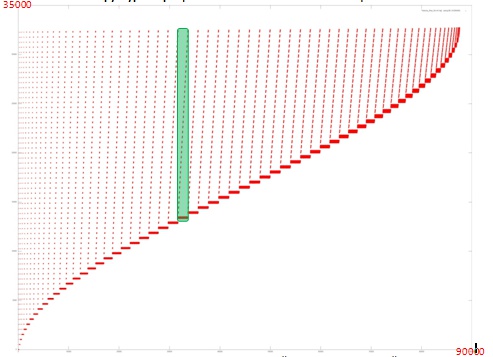
A memory access profile[12][13] is illustrated in Fig. 3 for an implementation of the Cholesky algorithm with a single working array. In this profile, hence, only the elements of this array are referenced. The above-illustrated implementation consists of a single main stage; in its turn, this stage consists of a sequence of similar iterations. An example of such an iteration is highlighted in green.
From Fig.3 it follows that, at each [math]i[/math]th iteration, all the addresses starting with a certain one are being used and the address of the first processed element increases with increasing [math]i[/math]. We should also note that, at each iteration, the number of memory accesses increases up to the middle of the algorithm; after that, this number decreases down to the end of the algorithm. This fact allows us to conclude that the data processed by the algorithm are used nonuniformly and that many iterations (especially at the beginning of the process) use a large amount of data, which decreases the memory access locality.
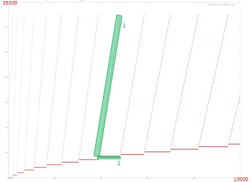
In this case, however, the structure of iterations is the main factor influencing the memory access locality. Fig.4 illustrates a fragment of the memory access profile for several first iterations.
From Fig.4 it follows that each iteration consists of two different fragments. The first fragment is the serial access to the addresses starting with a certain initial address; each element of the working array is rarely referenced. This fragment possesses a good spatial locality, since the step in memory between the adjacent memory references is not large; however, its temporal locality is bad, since the data are rarely reused.
The locality of the second fragment is much better, since a large number of references are made to the same data, which ensures a large degree of spatial and temporal locality than that of the first fragment.
We can also estimate the overall locality of these two fragments for each iteration. However, it is reasonable to consider the structure of each fragment in more detail.
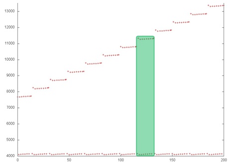
Fig.5 illustrates a part of a single iteration and shows that the structure of the above two fragments is more complicated than it can be concluded from Fig.4. In particular, each step of fragment 1 consists of several references to adjacent addresses and the memory access is not serial. Fragment 2 consists of repetitive iterations; each step of fragment 1 corresponds to a single iteration of fragment 2 (highlighted in green in Fig.5). This fact indicates that, in order to exactly understand the local profile structure, it is necessary to consider this profile on the level of individual references.
It should be noted that the conclusions made on the basis of Fig.5 supplement the general knowledge on the structure of the memory access profile, whereas the conclusions on the locality of the above two fragments made on the basis of Fig.4 remain valid.
2.2.1.2 Quantitative estimation of locality
The main fragment of the implementation used to obtain the quantitative estimates is given here (the Kernel function). The startup conditions are discussed here.
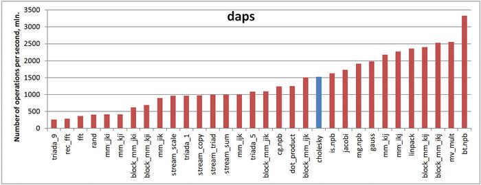
The first estimate is made on the basis of the daps characteristic used to evaluate the number of write and read operations per second. This characteristic is similar to the flops estimate for memory access and is an estimate of the memory usage performance rather than an estimate of locality. However, the daps characteristic is a good information source and can be used to compare with the results obtained according to the cvg characteristic.
Fig.6 illustrates the daps characteristics for a number of implementations of some widespread algorithms. The values of this characteristic are given in increasing order: a higher performance level corresponds to a larger value of daps. From this figure it follows that the Cholesky algorithm is characterized by a sufficiently large rate of memory usage; however, this rate is lower than that of the LINPACK test or the Jacobi method.
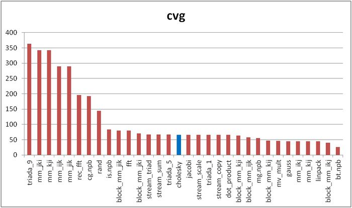
The cvg characteristic is used to obtain a more machine-independent estimate of locality and to specify the frequency of fetching data to the cache memory. A lesser value of cvg corresponds to a higher level of locality and to a smaller number of the above fetching procedure.
Fig.7 shows the cvg values for the same implementations presented in Fig.6. These values are given in decreasing order: the higher locality level corresponds to a smaller cvg value. From this figure it follows that the Cholesky algorithm occupies a lower position than it has in the performance list given in Fig.6 for the daps characteristic.
2.3 Possible methods and considerations for parallel implementation of the algorithm
An analysis of the algorithm’s structure allows one to conclude that a large variety of its parallel implementations can be proposed. In the second version (see «Implementation peculiarities of the serial algorithm»), for example, all the inner loops are parallel, whereas, in the first version, only the inner loop over [math]J[/math] is parallel. Nevertheless, a simple parallelization technique causes a large number of data transfer between the processors at each step of the outer loop; this number is almost comparable with the number of arithmetic operations. Hence, it is reasonable to partition the computations into blocks with the corresponding partitioning of the data arrays before the allocation of operations and data between the processors of the computing system in use.
A good-enough decision depends on the features of a particular computer system. If the nodes of a multiprocessor computer are equipped with conveyors, it is reasonable to compute several dot products at once in parallel. Such a possibility exists in the case of programmable logic devices; in this case, however, the arithmetic speed is limited by a slow serial square-root operation. In principle, it is possible to apply the so-called «skew» parallelism; however, this approach is not used in practice because of complexity in the control structure of the algorithm’s implementation.
2.4 Scalability of the algorithm and its implementations
2.4.1 Scalability of the algorithm
2.4.2 Scalability of of the algorithm implementation
Let us perform a scalability analysis of a particular implementation of the Cholesky algorithm according to the scalability methodology with the use of the Lomonosov supercomputer[14] installed at the Research Computing Center of Moscow State University. The description of this particular implementation is available at The C language implementation of the parallel Cholesky decomposition
- the number of processors [4 : 256] with the step equal to 4;
- the orders of matrices [1024 : 5120].
- minimum 0,11%;
- maximum 2,65%.
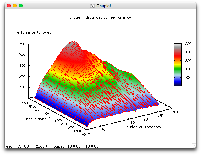
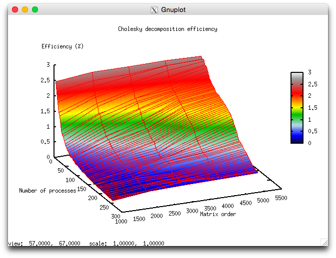
Figures 8 and 9 illustrate the performance and efficiency of the chosen parallel implementation of the Cholesky algorithm, depending on the startup parameters.
Below we discuss some estimations of scalability for the chosen implementation of the Cholesky decomposition.
- In accordance with the number of processes: -0,000593. If the number of processes increases, then the efficiency is reduced for the chosen range of the startup parameters, but this efficiency reduction is not very fast. Such a small reduction in performance variation can be explained by the fact that the general performance efficiency is very low (its maximum is equal to 2,65%); as a result, the algorithm’s efficiency is reduced down to one-tenth percent. Hence, this efficiency reduction is not intensive for the most part of the startup parameter range and becomes not fast with an increase of computational complexity. The efficiency reduction can also be explained by a fast increase in the excessive consumption of computational resources due to the management of parallel execution. When the computational complexity increases, the efficiency reduction is also fast if the number of processes is large. This confirms our assumption that the excessive consumption of computational resources prevail significantly over the computational cost.
- In accordance with the matrix order: 0,06017. When the matrix order increases, the performance efficiency also increases. This increase is faster if the number of processes used for solving the problem increases. This fact confirms our assumption that the matrix order essentially influences the performance efficiency. Our estimations shows that this efficiency significantly increases with an increase of the matrix order for the above range of the startup parameters. Taking into account the difference between the maximum and minimum efficiency (about 2,5%), we can conclude that such a growth of the efficiency is observed for the most part of the startup parameter range.
- In accordance with the two directions of parameter variation: 0,000403. If the computational complexity and the number of processes become larger, then the performance efficiency increases slowly with small jumps.
2.5 Dynamic characteristics and efficiency of the algorithm implementation
For our experiments we used the ScaLAPACK implementation for the Cholesky decomposition from the MKL library (the pdpotrf method). All results were obtained on the "Lomonosov" supercomputer[15]. For the experiments we used the Intel Xeon X5570 processors with 94 Gflops peak performance and the Intel compiler with -O2 option. The figures below illustrate the Cholesky decomposition implementation efficiency (the case of lower triangular matrices) for the matrix order 80000 and 256 processes.
Fig.10 shows that, during the runtime of the program, the processor usage level is about 50%. That is a good result for programs executed without the usage of the Hyper Threading technology.
Fig.11 shows the number of floating point operations per second during the Cholesky decomposition exection time. To the end of each iteration, the number of opertations increases intensively.
From Fig.12 it follows that the number of L1 cache-misses is large enough (about 25 millions per second on the average for all nodes).
From Fig.13 it follows that the number of L3 cache-misses is still large (about 1.5 millions/second). This fact indicates that the matrix order is large and the data do not fit in the cache.
From Fig.14 it follows that, during the execution time, the memory access is intensive enough and remains on approximately the same level.
From Fig.15 it follows that, to the end of each iteration, the number of memory write operations decreases rather considerably. This situation corelates with the increase in the number of floating point operations and can be explained by the fact the overheads are reduced and the efficiency increases when the number of memory write operations decreases.
From Fig.16 follows that the communication network is intensively used at each interation. To the end of each iteration, the data transfer intensity increases significantly. This fact indicates that, to the end of each iteration, the data exchange increases among the processes.
The Infiniband data transfer rate in packets per second shows a relatively uniform dispersion of maximum, minimum and average values compared to the bytes-per-second diagram. This shows that the processes are probably exchanging messages of varying lengths: an indication of unevenly distributed data. Network utilization is also intensified by the end of each iteration.
Fig.18 shows that the number of processes ready for the execution (LoadAvg) remains constant and is equal to 8 throughout the program run. This shows that the program is operating in a stable manner, with eight processes on each node. When the octa-core computing nodes are used, this indicates a rational and static loading of hardware resources by computing processes.
Overall, the data obtained from the monitoring system allows one to come to the conclusion that the program under study was working in an efficient and stable manner. The memory and communication environment usage is intensive, which can lead to an efficiency reduction with an increase of the matrix order or the number of processors in use.
2.6 Conclusions for different classes of computer architecture
Analyzing the performance of the ScaLAPACK library on supercomputers, we can conclude that, for large values of the matrix order [math]n[/math], the data exchanges reduce the execution efficiency, but to a smaller extent than the nonoptimality in the organization of computations within a single node. At the first stages, hence, it is necessary to optimize not a block algorithm but the subroutines used on individual processors, such as the dot Cholesky decomposition, matrix multiplications, etc. A number of possible directions of such an optimization are discussed below.
Generally speaking, the efficiency of the Cholesky algorithm cannot be high for parallel computer architectures. This fact can explained by the following property of its information structure: the square-root operations are the bottleneck of the Cholesky algorithm in comparison with the division operations or with the [math]a - bc[/math] operations, since these operations can easily be conveyorized or distributed among the nodes. In order to enhance the performance efficiency on parallel computers, hence, it is reasonable to use not the original Cholesky algorithm but its well-known modification without square-root operations; see the matrix decomposition in the form [math]L D L^T[/math][16].
2.7 Existing implementations of the algorithm
The dot version of the Cholesky algorithm is implemented in the basic libraries produced in Russia and in the libraries produced in western countries (for example, in LINPACK, LAPACK, ScaLAPACK, and others).
In the Russian libraries, as a rule, the accumulation mode is implemented to reduce the effect of round-off errors. In order to save computer memory, a packed representation of the matrices [math]A[/math] and [math]L[/math] is also used in the form of one-dimensional arrays.
In the modern western libraries, the dot Cholesky implementations are based on its LINPACK implementation utilizing the BLAS library. The dot product is computed in BLAS with no accumulation mode, but this mode can easily be implemented by minor modifications of the SDOT subprogram included in the BLAS library.
It is interesting to note that the original Cholesky decomposition is available in the largest western libraries, whereas the faster [math]LU[/math] decomposition algorithm without square-root operations is used only in special cases (for example, for tridiagonal matrices) when the number of diagonal elements is comparable with the number of off-diagonal elements.
3 References
- ↑ Commandant Benoit, Note sur une méthode de résolution des équations normales provenant de l'application de la méthode des moindres carrés à un système d'équations linéaires en nombre inférieur à celui des inconnues (Procédé du Commandant Cholesky), Bulletin Géodésique 2 (1924), 67-77.
- ↑ Banachiewicz T. Principles d'une nouvelle technique de la méthode des moindres carrês. Bull. Intern. Acad. Polon. Sci. A., 1938, 134-135.
- ↑ Banachiewicz T. Méthode de résoltution numérique des équations linéaires, du calcul des déterminants et des inverses et de réduction des formes quardatiques. Bull. Intern. Acad. Polon. Sci. A., 1938, 393-401.
- ↑ Voevodin V.V. Computational foundations of linear algebra Moscow: Nauka, 1977.
- ↑ Voevodin V.V., Kuznetsov Yu.A. Matrices and computations, Moscow: Nauka, 1984.
- ↑ Faddeev D.K., Faddeeva V.N. Computational methods in linear algebra. Moscow-Leningrad: Fizmatgiz, 1963.
- ↑ Kaporin I.E. High quality preconditioning of a general symmetric positive definite matrix based on its UTU + UTR + RTU-decomposition. Numer. Lin. Algebra Appl. (1998) Vol. 5, No. 6, 483-509.
- ↑ Kaporin I.E., Kon'shin I.N. Parallel solution of symmetric positive definite systems based on decomposition into overlapping blocks. Zhurn. Vychisl. Matem. i Matem. Fiziki. (2001) Vol. 41, No. 4, 515–528.
- ↑ Voevodin V.V. Mathematical foundations of parallel computing. Moscow: Moscow University Press, 1991. 345 pp.
- ↑ Voevodin V.V., Voevodin Vl.V. Parallel computing. St. Petersburg : BHV-Petersburg, St. 2002. 608 pp.
- ↑ Frolov A.V. Design principles and description of the Sigma language. Preprint N 236. Moscow: Institute of Numerical Mathematics, 1989.
- ↑ Voevodin Vad.V. Visualization and analysis of memory access profile Vestnik South-Ural State University (2011) No. 8, 76–84.
- ↑ Voevodin Vl.V., Voevodin Vad.V. The fortunate locality of supercomputers. Otkrytye Sistemy (2013) No. 9, 12-15.
- ↑ Voevodin Vl.V., Zhumatii S.A., Sobolev S.I., Antonov A.S., Bryzgalov P.A., Nikitenko D.A., Stefanov K.S., Voevodin Vad.V. The Lomonosov supercomputer in practice. Otkrytye Sistemy (2012) No. 7, 36-39.
- ↑ Voevodin Vl.V., Zhumatii S.A., Sobolev S.I., Antonov A.S., Bryzgalov P.A., Nikitenko D.A., Stefanov K.S., Voevodin Vad.V. The Lomonosov supercomputer in practice. Otkrytye Sistemy (2012) No. 7, 36-39.
- ↑ Krishnamoorthy A., Menon D. Matrix Inversion Using Cholesky Decomposition. 2013. eprint arXiv:1111.4144

