Single-qubit transform of a state vector
| Single-qubit transform of a state vector | |
| Sequential algorithm | |
| Serial complexity | [math]3 \cdot 2^n[/math] |
| Input data | [math]2^n+4[/math] |
| Output data | [math]2^n[/math] |
| Parallel algorithm | |
| Parallel form height | [math]2[/math] |
| Parallel form width | [math]2^{n+1}[/math] |
Primary authors of this description: A.Yu.Chernyavskiy, Vad.V.Voevodin (Section 2.2)
Contents
- 1 Properties and structure of the algorithm
- 1.1 General description of the algorithm
- 1.2 Mathematical description of the algorithm
- 1.3 The computational kernel of the algorithm
- 1.4 Macro structure of the algorithm
- 1.5 Implementation scheme of the serial algorithm
- 1.6 Serial complexity of the algorithm
- 1.7 Information graph
- 1.8 Parallelization resource of the algorithm
- 1.9 Input and output data of the algorithm
- 1.10 Properties of the algorithm
- 2 Software implementation of the algorithm
- 2.1 Implementation peculiarities of the serial algorithm
- 2.2 Locality of data and computations
- 2.3 Возможные способы и особенности параллельной реализации алгоритма
- 2.4 Масштабируемость алгоритма и его реализации
- 2.5 Динамические характеристики и эффективность реализации алгоритма
- 2.6 Выводы для классов архитектур
- 2.7 Существующие реализации алгоритма
- 3 Литература
1 Properties and structure of the algorithm
1.1 General description of the algorithm
The algorithm simulates an action of a single-qubit quantum gate on a state vector. [1] [2] [3]
This algorithm is often a subroutine and is used iteratively to the different qubits of a state. For example, it's used for the quantum algorithms simulation and the analysis of quantum entanglement. As for the most of the classical algorithms in quantum information science, the described algorithm shows the exponential data growth with respect to the number of qubits. This fact leads the necessity of a supercomputer usage for the practically important tasks.
1.2 Mathematical description of the algorithm
Input data:
Integer parameters [math]n[/math] (the number of qubits) and [math]k[/math] (the number of the affected qubit).
A complex [math]2 \times 2[/math] matrix [math]U = \begin{pmatrix} u_{00} & u_{01}\\ u_{10} & u_{11} \end{pmatrix}[/math] of a single-qubit transform.
A complex [math]2^n[/math]-dimensional vector [math]v,[/math] which denotes the initial state of a quantum system.
Output data: the complex [math]2^n[/math]-dimensional vector [math]w,[/math] which corresponds to the quantum state after the transformation.
The single-qubit transform can be represented as follows:
The output state after the action of a transform [math]U[/math] on the [math]k-[/math]th qubit is [math]v_{out} = I_{2^{k-1}}\otimes U \otimes I_{2^{n-k}},[/math] where [math]I_{j}[/math] is the [math]j-[/math]dimensional identity matrix, and [math]\otimes[/math] denotes the tensor (Kronecker) product.
However, the elements of the output vector can be represented in more computationally useful direct form:
- [math] w_{i_1i_2\ldots i_k \ldots i_n} = \sum\limits_{j_k=0}^1 u_{i_k j} v_{i_1i_2\ldots j_k \ldots i_n} = u_{i_k 0} v_{i_1i_2\ldots 0_k \ldots i_n} + u_{i_k 1} v_{i_1i_2\ldots 1_k \ldots i_n} [/math]
A tuple-index [math]i_1i_2\ldots i_n[/math] denotes the binary form of an array index.
1.3 The computational kernel of the algorithm
The computational kernel of the single-qubit transform can be composed of [math]2^n[/math] calculations of the elements of the output vector [math]w.[/math] The computation of each element consists of two complex multiplication and one complex addition opearations. Moreover we need to compute an indexes [math]i_1i_2\ldots 0_k \ldots i_n,[/math] and the [math]i_k[/math] bits, these computations needs the bitwise operations.
1.4 Macro structure of the algorithm
As noted in the description of the computational kernel, the main part of the algorithm consists of the independent computations of the output vector elements.
1.5 Implementation scheme of the serial algorithm
For [math]i[/math] from [math]0[/math] to [math]2^n-1[/math]
- Calculate the element [math]i_k[/math] of the binary representation of the index [math]i.[/math]
- Calculate indexes [math]j[/math] with binary representation [math]i_1i_2\ldots \overline{i_k} \ldots i_n,[/math] where the overline denotes the bit-flip.
- Calculate [math]w_i = u_{i_k i_k}\cdot v_{i} + u_{i_k \overline{i_k}}\cdot v_j.[/math]
1.6 Serial complexity of the algorithm
The following number of operations is needed for the single-qubit transform:
- [math]2^{n+1}[/math] complex multiplications;
- [math]2^n[/math] complex additions;
- [math]2^n[/math] [math]k[/math]-th bit reads;
- [math]2^n[/math] [math]k[/math]-th bit writes.
Note, that the algorithm are often used iteratively, that's the the bit operations (3-4) can be performed once in the beginning of computations. Moreover, they can be avoided by the usage of additions and bitwise multiplications with the [math]2^k,[/math] that can be also calculated once for each [math]k.[/math]
1.7 Information graph
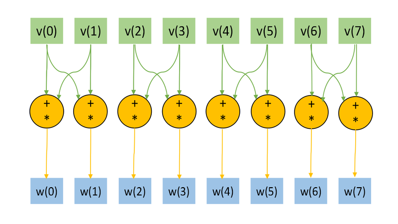
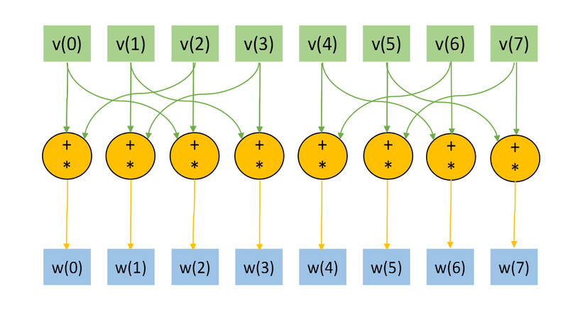
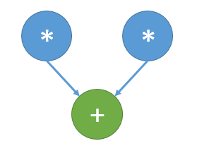
The Figs. 1 and 2 shows the information graph for the paramters [math]n=3, k=1[/math] and [math]n=3, k=2.[/math] The graphs are presented without a transformation matrix [math]U,[/math] because its small size in comparison with a input and output data. Fig.3 shows the main operation, which is denoted by orange on Figs.1-2.
The representation with an input and data and the "folded" triple operation is useful for the understanding of the memory locality. Note, the the structure of an information graph strongly depends on the parameter [math]k.[/math]
1.8 Parallelization resource of the algorithm
As we can see on the information graph, the direct algorithm of one-qubit transform simulation has the very high parallelization resource, because all computations of different output vector elements can be made independently. Two multiplication operations needed for the computation of each output vector element also can be done in parallel.
So, there are only two levels of computations:
- [math]2^{n+1}[/math] multiplications.
- [math]2^n[/math] additions.
1.9 Input and output data of the algorithm
Input data:
- [math]2^n[/math]-dimensional complex state vector [math]u.[/math] In most cases thу vector is normalized to 1.
- [math]2[/math]-dimensional unitary matrix [math]U[/math].
- The number (index) of the affected qubit [math]q[/math].
Output data:
- The [math]2^n[/math]-dimensional complex output state vector [math]w.[/math].
Amount of input data: [math]2^n+4[/math] complex numbers and [math]1[/math] integer parameter.
Amount of output data: [math]2^n[/math] complex numbers.
1.10 Properties of the algorithm
The ratio of the serial complexity to the parallel complexity is exponential (an exponent transforms to a constant).
The computational power of the algorithm considered as the ratio of the number of operations to the amount of input and output data is constant.
2 Software implementation of the algorithm
2.1 Implementation peculiarities of the serial algorithm
The function of the single-qubit transform may be represented in C language as:
void OneQubitEvolution(complexd *in, complexd *out, complexd U[2][2], int nqubits, int q)
{
	//n - number of qubits
        //q - index of the affected qubit

	int shift = nqubits-q;
	//All bits are zeros, except the bit correspondent to the affected qubit.
	int pow2q=1<<(shift);

	int N=1<<nqubits;
	for	(int i=0; i<N; i++)
	{
		//Making the changing bit zero
		int i0 = i & ~pow2q;

		//Setting the changing bit value
		int i1 = i | pow2q;

		//Getting the changing bit value
		int iq = (i & pow2q) >> shift;

		out[i] = U[iq][0] * in[i0] + U[iq][1] *in[i1];
	}
}
Note, that the huge part of the computation and code logic consists of the bit operations, but this can be avoided. In most cases, single-qubit transform is just as a subroutine and is used sequentially many times. Moreover, indexes i0, i1, and iq depends only on the parameters n and q. The n is fixed, and we can calculate these indexes in the beginning of computations for every parameter q, and we need only 3n integers to store the data, when the input and output data growths exponentially. It's obvious that such optimization is critically needed for the implementations of the algorithm for the hardware and software with slow bit operations (for example, Matlab).
2.2 Locality of data and computations
Despite of the great parallelization resource, practical implementations have a bad locality.
From the mathematical description and information graphs for the different parameter q (the number of affected qubit), we can see for the single work of the algorithm it's easy to achieve the ideal locality by the permutation of qubits. Thus, if we move the q-th qubit to the last place, we achieve the sequential transfers only between local elements.
However, the single-qubit transform is almost always used sequentially as a subroutine on a common state with different parameter q. As we can see from the mathematical description and Figs. 1-2, it is impossible to achieve good locality.
2.2.1 Locality of implementation
2.2.1.1 Structure of memory access and a qualitative estimation of locality
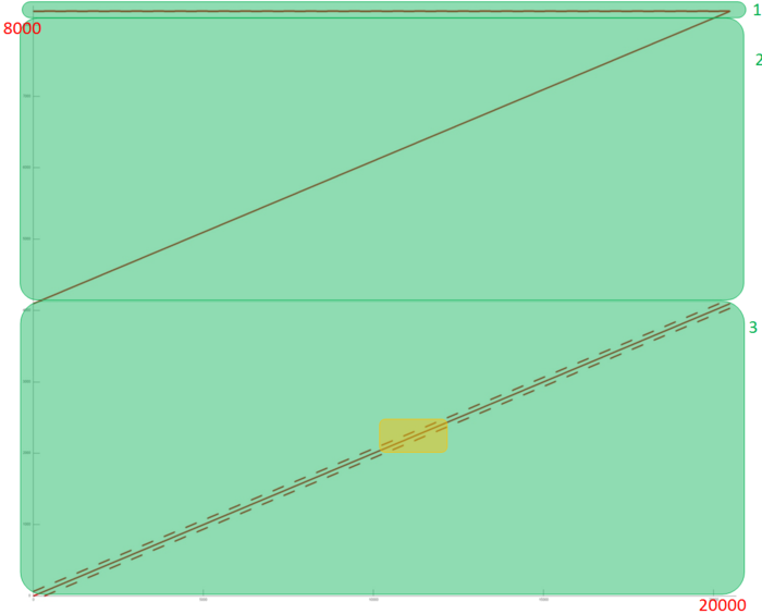
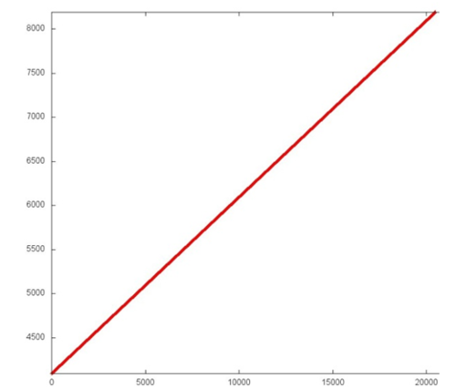
На рис. 1 представлен профиль обращений в память для вычисления однокубитного преобразования вектора-состояния. Данный профиль состоит из обращений к трем массивам, фрагменты для отдельных массивов выделены на рис. 1 зеленым цветом. Из общего профиля можно увидеть, что обращения редко используются повторно, по крайней мере в случае фрагментов 2 и 3. При этом обращения к близко расположенным друг к другу данным выполняются рядом. Рассмотрим выделенные фрагменты поближе.
Отдельно фрагмент 1 представлен на рис. 2. Видно, что данный массив состоит всего из 4-х элементов, к которым постоянно выполняются обращения. Такой фрагмент обладает очень высокой локальностью, поскольку постоянно используются ранее запрошенные данные.
Далее, рассмотрим фрагмент 2 (рис. 3). Здесь все еще проще – выполняется обычный последовательный перебор всех элементов массива. Такой фрагмент обладает высокой пространственной локальностью, однако очень низкой временной (данные не используются повторно).
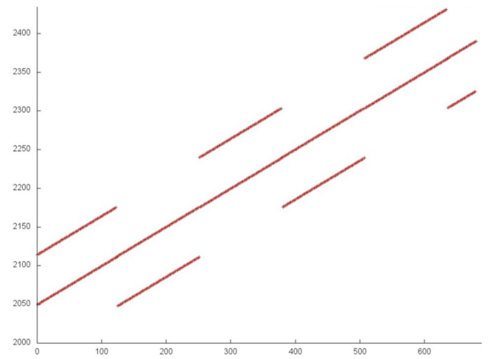
Наиболее интересным представляется фрагмент 3. Его небольшой фрагмент, выделенный на рис. 1 желтым, представлен на рис. 4. Однако при ближайшем рассмотрении оказывается, что данный фрагмент тоже просто устроен, хотя и немного сложнее предыдущих.
В данном случае также виден в центре последовательный перебор всех элементов массива, параллельно с которым выполняются обращения либо к элементам с большим или меньшим виртуальным адресом. Отметим, однако, что эта разница между виртуальными адресами, судя по всему, больше 64 байт (длины строки), что может служить причиной возникновения большого числа кэш-промахов.
В общем можно сказать, что общий профиль обращений в память обладает достаточно высокой пространственной локальностью, поскольку большинство обращений образуют последовательные переборы элементов массивов, однако временная локальность низка – данные практически не используются повторно.
2.2.1.2 Количественная оценка локальности
Основной фрагмент реализации, на основе которого были получены количественные оценки, приведен здесь (функция Kernel). Условия запуска описаны здесь.
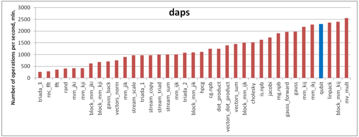
Первая оценка выполняется на основе характеристики daps, которая оценивает число выполненных обращений (чтений и записей) в память в секунду. Данная характеристика является аналогом оценки flops применительно к работе с памятью и является в большей степени оценкой производительности взаимодействия с памятью, чем оценкой локальности. Однако она служит хорошим источником информации, в том числе для сравнения с результатами по следующей характеристике cvg.
На рисунке 5 приведены значения daps для реализаций распространенных алгоритмов, отсортированные по возрастанию (чем больше daps, тем в общем случае выше производительность). Можно увидеть, что производительность работы с памятью для этой программы высока – значение daps примерно на уровне теста Linpack. Видимо, низкая временная локальность в данном случае компенсируется высокой пространственной локальностью.
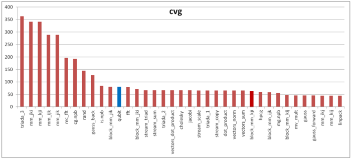
Вторая характеристика – cvg – предназначена для получения более машинно-независимой оценки локальности. Она определяет, насколько часто в программе необходимо подтягивать данные в кэш-память. Соответственно, чем меньше значение cvg, тем реже это нужно делать, тем лучше локальность.
На рисунке 6 приведены значения cvg для того же набора реализаций, отсортированные по убыванию (чем меньше cvg, тем в общем случае выше локальность). Можно увидеть, что, в отличие от daps, cvg оценивает локальность данной программы как достаточно низкую. В частности, значение cvg для Linpack заметно меньше, в то время как значения daps практически совпадали.
Одна из возможных причин этого – влияние арифметических операций. Может получиться, что данные из памяти не будут запрашиваться, пока арифметические операции не будут выполнены; это приводит к простою подсистемы памяти. Соответственно, если в одной программе таких операций нет, а в другой - есть, то daps в первом случае будет выше. При этом cvg не поменяется, поскольку эта оценка не зависит от времени выполнения.
В данном случае арифметических операций практически нет (в отличие от некоторых других программ), поэтому daps может показывать более высокие результаты, в то время как cvg показывает достаточно низкую оценку.
2.3 Возможные способы и особенности параллельной реализации алгоритма
Основной способ параллельной реализации очевиден - необходимо распараллеливание основного цикла (параллельное вычисление различных компонент выходного вектора-состояния) и, желательно, операций умножения. На машинах с общей памятью такой вариант распараллеливания приводит к ускорению, близкому к максимально-возможному. Однако, данный способ сталкивается с проблемами локальности данных. Анализируя математическая описание и информационные графы алгоритма легко видеть, что при использовании большого числа узлов с собственной памятью количество необходимых пересылок между узлами становится сопоставимым с количеством вычислений, что приводит к существенной потере эффективности. Возможны разные пути частичного решения этой проблемы, например, кэширование или использование парадигмы программирования SHMEM, однако, столь сильная нелокальность использования данных всё равно не позволяет добиться хорошей эффективности.
2.4 Масштабируемость алгоритма и его реализации
2.4.1 Масштабируемость алгоритма
2.4.2 Масштабируемость реализации алгоритма
Because of the constant height of the parallel form the algorithm is very good scalable for the shared memory implementation. But the usage of the distributed memory leads to the locality problems.
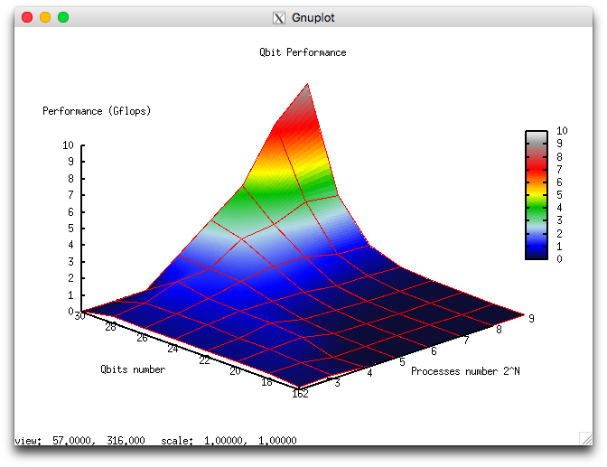
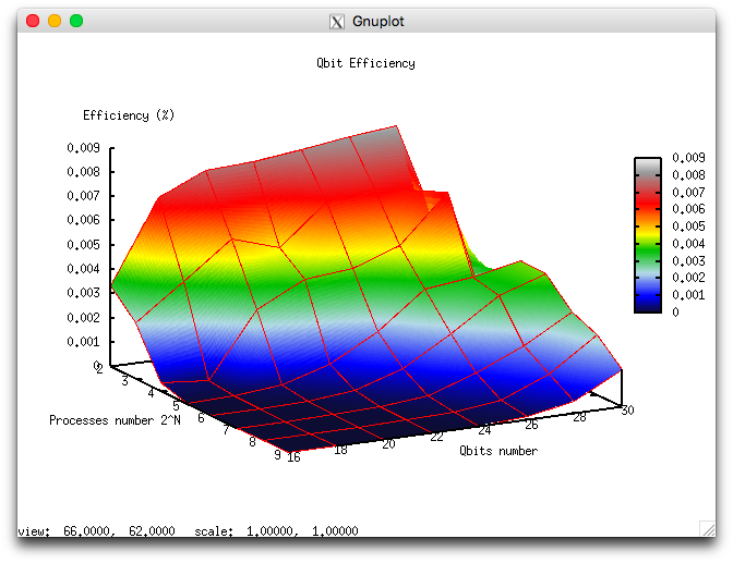
Let us perform a scalability analysis of a particular implementation of the Cholesky algorithm according to the scalability methodology with the use of the Lomonosov supercomputer[4] installed at the Research Computing Center of Moscow State University.
- the number of processors [4 : 512] with the powers of 2 step;
- the number of qubits [16 : 32] with step 2.
- minimum 0.000003%;
- maximum 0.008%.
The following Figures illustrate the performance and efficiency of the chosen parallel implementation of the Cholesky algorithm, depending on the startup parameters.
for the efficiency are shown at Figure 2b. It can be seen, that efficiency is quite low, but it grows fast with the number of qubits and remains constant with simultaneous increasing of the number of processors and qubits.
The following parallel implementation of the algorithm was used: parallel impplementation of single-qubit transform.
2.5 Динамические характеристики и эффективность реализации алгоритма
The implementation of the algorithm used for the analysis is available here. All results were obtained on the "GraphIT!" supercomputer. For the experiments we used the Intel Xeon X5570 processors with 94 Gflops peak performance and the Gnu 4.4.7 compiler.
The CPU usage diagram shows that the average CPU usage during almost all the runtime of the program is about 50%. This fact shows high load, when 8 processes works on 8 processors without HyperThreading technology. It means, that the usage of all physical cores is near to 100%.
Diagram for the number of floating point operations per second shows high performane. The peak performance is 300 mln. flops, and about 70 mln. flops on average between nodes. This fact may indicate the dizbalans of the computations with rather high performance.
На графике кэш-промахов первого уровня видно, что число промахов достаточно высокое и находится на уровне 4 млн/сек для отдельных процессов и 1 млн/сек в среднем по всем процессам. Это указывает на достаточно высокую интенсивность вычислений и хорошую локальность данных, учитывая высокие показатели операций с плавающей точкой и на дисбаланс вычислений между процессами.
На графике кэш-промахов третьего уровня видно, что число промахов все еще достаточно высокое для параллельного приложения и находится на уровне 1 млн/сек в пике и около 250 тыс/сек в среднем по всем узлам. Отношение промахов L1/L3 около 4, что является средним показателем по таким задачам. Это также указывает на достаточно плохую локальность вычислений.
На графике чтений из памяти на наблюдается достаточно невысокая активность чтения из памяти процессами. Так как активно работает сразу большое число процессов, то и активность чтения различная между максимальным и средним значением указывает на дизбалас вычислений в прграмме. Активность немного ниже типичной для приложений такого класса.
Активность записи в память достаточно низкая, это вполне ожидаемо для такого алгоритма, и так же указывает на достаточно высокую локальность вычислений.
На графике числа процессов, ожидающих вхождения в стадию счета (Loadavg), видно, что на протяжении всей работы программы значение этого параметра постоянно и приблизительно равняется 3. Это свидетельствует о стабильной работе программы с работающим малым числом ядер на каждом вычислительном узле. Это подтверждает предположение о разбалансированности вычислений, потому как часть процессов не проводит активных вычислений. В целом, по данным системного мониторинга работы программы можно сделать вывод о том, что программа работала не очень эффективно, но с высоким дисбалансом нагрузки. Приложение имеет достаточно высокий ресурс для оптимизаций в ключе более рационального распределения нагрузки на вычислители.
2.6 Выводы для классов архитектур
Исходя из высочайшей возможности параллелизации и при этом наличия существенной нелокальности обращения к данным, эффективная и хорошо масштабируемая параллельная реализация алгоритма однокубитного квантового преобразования легко достижима на машинах с общей памятью. Реализация же на машинах с разделяемой памятью имеет низкую эффективность и требует специальных подходов для уменьшения времени работы. Можно отметить, что данная задача является хорошим плацдармом для разработки методов решения задач с интенсивным использованием данных и низкой локальностью.
2.7 Существующие реализации алгоритма
3 Литература
- ↑ Kronberg D. A., Ozhigov Yu. I., Chernyavskiy A. Yu. Algebraic tools for quantum information. (In Russian)
- ↑ Preskill J. Lecture notes for physics 229: Quantum information and computation //California Institute of Technology. – 1998.
- ↑ Nielsen, Michael A., and Isaac L. Chuang. Quantum computation and quantum information. Cambridge university press, 2010.
- ↑ Voevodin Vl.V., Zhumatii S.A., Sobolev S.I., Antonov A.S., Bryzgalov P.A., Nikitenko D.A., Stefanov K.S., Voevodin Vad.V. The Lomonosov supercomputer in practice. Otkrytye Sistemy (2012) No. 7, 36-39.
