Single-qubit transform of a state vector
| Single-qubit transform of a state vector | |
| Sequential algorithm | |
| Serial complexity | [math]3 \cdot 2^n[/math] |
| Input data | [math]2^n+4[/math] |
| Output data | [math]2^n[/math] |
| Parallel algorithm | |
| Parallel form height | [math]2[/math] |
| Parallel form width | [math]2^{n+1}[/math] |
Primary authors of this description: A.Yu.Chernyavskiy, Vad.V.Voevodin (Section 2.2)
Contents
- 1 Properties and structure of the algorithm
- 1.1 General description of the algorithm
- 1.2 Mathematical description of the algorithm
- 1.3 The computational kernel of the algorithm
- 1.4 Macro structure of the algorithm
- 1.5 Implementation scheme of the serial algorithm
- 1.6 Serial complexity of the algorithm
- 1.7 Information graph
- 1.8 Parallelization resource of the algorithm
- 1.9 Input and output data of the algorithm
- 1.10 Properties of the algorithm
- 2 Software implementation of the algorithm
- 2.1 Implementation peculiarities of the serial algorithm
- 2.2 Locality of data and computations
- 2.3 Possible methods and considerations for parallel implementation of the algorithm
- 2.4 Scalability of the algorithm and its implementations
- 2.5 Dynamic characteristics and efficiency of the algorithm implementation
- 2.6 Conclusions for different classes of computer architecture
- 2.7 Existing implementations of the algorithm
- 3 References
1 Properties and structure of the algorithm
1.1 General description of the algorithm
The algorithm simulates an action of a single-qubit quantum gate on a state vector. [1] [2] [3]
This algorithm is often a subroutine and is used iteratively to the different qubits of a state. For example, it's used for the quantum algorithms simulation and the analysis of quantum entanglement. As for the most of the classical algorithms in quantum information science, the described algorithm shows the exponential data growth with respect to the number of qubits. This fact leads to the necessity of a supercomputer usage for the practically important tasks.
1.2 Mathematical description of the algorithm
Input data:
Integer parameters [math]n[/math] (the number of qubits) and [math]k[/math] (the number of the affected qubit).
A complex [math]2 \times 2[/math] matrix [math]U = \begin{pmatrix} u_{00} & u_{01}\\ u_{10} & u_{11} \end{pmatrix}[/math] of a single-qubit transform.
A complex [math]2^n[/math]-dimensional vector [math]v,[/math] which denotes the initial state of a quantum system.
Output data: the complex [math]2^n[/math]-dimensional vector [math]w,[/math] which corresponds to the quantum state after the transformation.
The single-qubit transform can be represented as follows:
The output state after the action of a transform [math]U[/math] on the [math]k-[/math]th qubit is [math]v_{out} = I_{2^{k-1}}\otimes U \otimes I_{2^{n-k}},[/math] where [math]I_{j}[/math] is the [math]j-[/math]dimensional identity matrix, and [math]\otimes[/math] denotes the tensor (Kronecker) product.
However, the elements of the output vector can be represented in more computationally useful direct form:
- [math] w_{i_1i_2\ldots i_k \ldots i_n} = \sum\limits_{j_k=0}^1 u_{i_k j} v_{i_1i_2\ldots j_k \ldots i_n} = u_{i_k 0} v_{i_1i_2\ldots 0_k \ldots i_n} + u_{i_k 1} v_{i_1i_2\ldots 1_k \ldots i_n} [/math]
A tuple-index [math]i_1i_2\ldots i_n[/math] denotes the binary form of an array index.
1.3 The computational kernel of the algorithm
The computational kernel of the single-qubit transform can be composed of [math]2^n[/math] calculations of the elements of the output vector [math]w.[/math] The computation of each element consists of two complex multiplication and one complex addition opearations. Moreover we need to compute an indexes [math]i_1i_2\ldots 0_k \ldots i_n,[/math] and the [math]i_k[/math] bits, these computations needs the bitwise operations.
1.4 Macro structure of the algorithm
As noted in the description of the computational kernel, the main part of the algorithm consists of the independent computations of the output vector elements.
1.5 Implementation scheme of the serial algorithm
For [math]i[/math] from [math]0[/math] to [math]2^n-1[/math]
- Calculate the element [math]i_k[/math] of the binary representation of the index [math]i.[/math]
- Calculate indexes [math]j[/math] with binary representation [math]i_1i_2\ldots \overline{i_k} \ldots i_n,[/math] where the overline denotes the bit-flip.
- Calculate [math]w_i = u_{i_k i_k}\cdot v_{i} + u_{i_k \overline{i_k}}\cdot v_j.[/math]
1.6 Serial complexity of the algorithm
The following number of operations is needed for the single-qubit transform:
- [math]2^{n+1}[/math] complex multiplications;
- [math]2^n[/math] complex additions;
- [math]2^n[/math] [math]k[/math]-th bit reads;
- [math]2^n[/math] [math]k[/math]-th bit writes.
Note, that the algorithm are often used iteratively, that's the the bit operations (3-4) can be performed once in the beginning of computations. Moreover, they can be avoided by the usage of additions and bitwise multiplications with the [math]2^k,[/math] that can be also calculated once for each [math]k.[/math]
1.7 Information graph
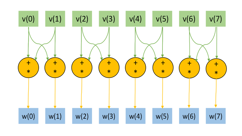
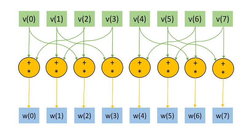
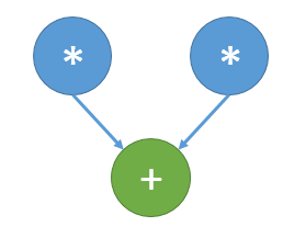
The Figs. 1 and 2 shows the information graph for the paramters [math]n=3, k=1[/math] and [math]n=3, k=2.[/math] The graphs are presented without a transformation matrix [math]U,[/math] because its small size in comparison with a input and output data. Fig.3 shows the main operation, which is denoted by orange on Figs.1-2.
The representation with an input and data and the "folded" triple operation is useful for the understanding of the memory locality. Note, the the structure of an information graph strongly depends on the parameter [math]k.[/math]
1.8 Parallelization resource of the algorithm
As we can see on the information graph, the direct algorithm of one-qubit transform simulation has the very high parallelization resource, because all computations of different output vector elements can be made independently. Two multiplication operations needed for the computation of each output vector element also can be done in parallel.
So, there are only two levels of computations:
- [math]2^{n+1}[/math] multiplications.
- [math]2^n[/math] additions.
1.9 Input and output data of the algorithm
Input data:
- [math]2^n[/math]-dimensional complex state vector [math]u.[/math] In most cases thу vector is normalized to 1.
- [math]2[/math]-dimensional unitary matrix [math]U[/math].
- The number (index) of the affected qubit [math]q[/math].
Output data:
- The [math]2^n[/math]-dimensional complex output state vector [math]w.[/math].
Amount of input data: [math]2^n+4[/math] complex numbers and [math]1[/math] integer parameter.
Amount of output data: [math]2^n[/math] complex numbers.
1.10 Properties of the algorithm
The ratio of the serial complexity to the parallel complexity is exponential (an exponent transforms to a constant).
The computational power of the algorithm considered as the ratio of the number of operations to the amount of input and output data is constant.
2 Software implementation of the algorithm
2.1 Implementation peculiarities of the serial algorithm
The function of the single-qubit transform may be represented in C language as:
void OneQubitEvolution(complexd *in, complexd *out, complexd U[2][2], int nqubits, int q)
{
	//n - number of qubits
        //q - index of the affected qubit

	int shift = nqubits-q;
	//All bits are zeros, except the bit correspondent to the affected qubit.
	int pow2q=1<<(shift);

	int N=1<<nqubits;
	for	(int i=0; i<N; i++)
	{
		//Making the changing bit zero
		int i0 = i & ~pow2q;

		//Setting the changing bit value
		int i1 = i | pow2q;

		//Getting the changing bit value
		int iq = (i & pow2q) >> shift;

		out[i] = U[iq][0] * in[i0] + U[iq][1] *in[i1];
	}
}
Note, that the huge part of the computation and code logic consists of the bit operations, but this can be avoided. In most cases, single-qubit transform is just as a subroutine and is used sequentially many times. Moreover, indexes i0, i1, and iq depends only on the parameters n and q. The n is fixed, and we can calculate these indexes in the beginning of computations for every parameter q, and we need only 3n integers to store the data, when the input and output data growths exponentially. It's obvious that such optimization is critically needed for the implementations of the algorithm for the hardware and software with slow bit operations (for example, Matlab).
2.2 Locality of data and computations
Despite of the great parallelization resource, practical implementations have a bad locality.
From the mathematical description and information graphs for the different parameter q (the number of affected qubit), we can see for the single work of the algorithm it's easy to achieve the ideal locality by the permutation of qubits. Thus, if we move the q-th qubit to the last place, we achieve the sequential transfers only between local elements.
However, the single-qubit transform is almost always used sequentially as a subroutine on a common state with different parameter q. As we can see from the mathematical description and Figs. 1-2, it is impossible to achieve good locality.
2.2.1 Locality of implementation
2.2.1.1 Structure of memory access and a qualitative estimation of locality
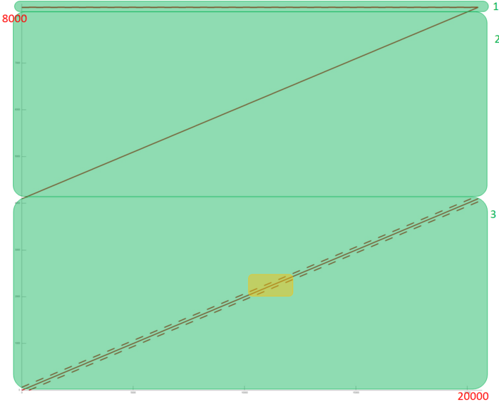
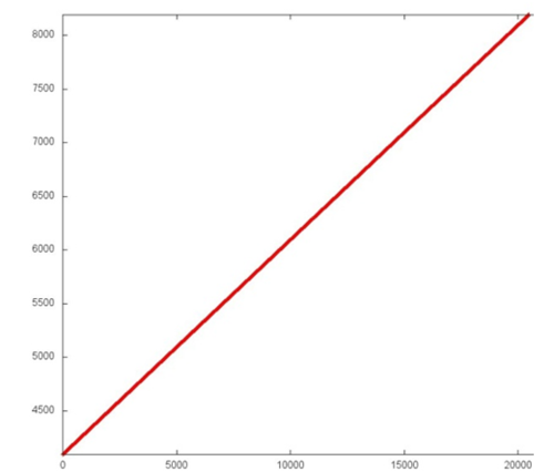
As it was mentioned above, the locality of computations depends on the parameter q (the index of the affected qubit). Firstly, let's examine the memory access for the fixed parameter q (n=12, q=6). A memory access profile is illustrated in Fig. 4. The profile consists of the accesses to three different arrays, these arrays are emphasized on Fig. 4 by the green color. We can see that for the fragmets 2 and 3 memory accesses don't repeat, but the are closely situated. Let's examine the fragments closely.
The fragment 1 is shown on Fig. 5. This array corresponds to the transformation matrix and consists only of 4 elements, so the locality is very high.
The fragment 2 (Fig. 5) shows the simple sequential access to all the array elements. Such fragment has very high spatial and very low time locality (data isn't accessed repeatedly).
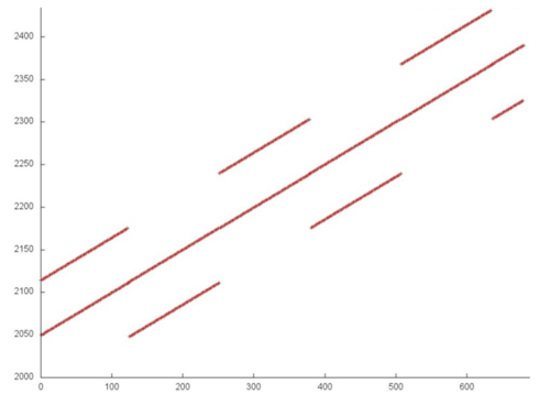
The fragment 3 is most interesting. Its part is shown on Fig. 7. Here we can see again the sequential access to the array elements, but with parallel access to elements with higher or lower virtual addresses.
Now, let's examine the dependence of the memory-access profile on the parameter q (the number of affected qubit). Fig. 8 shows the profile for different values of the parameter. As we can see, the fragments 1 and 2 don't change, but the third fragment change its shift for the parallel access. This makes it difficult to effectively implement the algorithm for the distributed memory.
2.2.1.2 Quantitative estimation of locality
The main implementation fragment, which is used in all quantitative assessments, is shown here(Kernel function). Launch conditions are described here. The number of qubits was n=24 and the index of affected qubit was q=12.
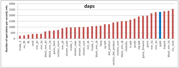
The first estimate is based on daps, which assesses the number of memory access operations (reads and writes) per second. Similar to flops, this tool is used to evaluate memory access performance, rather than locality. But it is still a good source of information, particularly in combination with the next estimate – cvg.
Fig.9 shows daps values for implementations of common algorithms, sorted in ascending order (the higher the daps, the better the performance in general). One can see, that the performance is good. The daps value is close to the Linpack test. It seems, that low temporal locality is compensated by spatial locality.
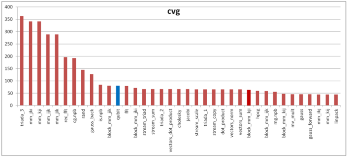
The second tool – cvg – is intended to obtain a more machine-independent locality assessment. It determines how often a program needs to pull data to cache memory. Respectively, the smaller the cvg value, the less frequently data needs to be called to cache, and the better the locality.
Fig.10 shows cvg values for the same set of implementations sorted in descending order (the smaller the cvg, the higher the locality in general). As we can see, the cvg is not so gooв as daps, and it's noticeably higher than for the Linpack test.
One of the possible explanations is an effect of arithmetic operations. There is a chance, that data is not read until the end of the arithmetic operations, this leads to the memory system dead time. Consequently, daps value for the program without arithmetic operations is lower, whenever cvg remains constant, and considered algorithm has very low amount of arithmetic operations.
As shown above, the locality depends on the parameter q (the index of affected qubit). So, it's important to analyze the daps and cvg values with respect to q. Both values were calculated for n=24 and all possible q values. Daps value remains constant (possibly, because of the small amount of arithmetic operations). Cvg changes on some critical value of q (is 80 for q < 15 and 55 for q > 15). It seems, that this change is due to the gap between fetched data in the third fragment, that was described in structure of memory access.
2.3 Possible methods and considerations for parallel implementation of the algorithm
The main method of the parallelization is obvious: we need to parallelize the main loop (independent computations of the elements of the output vector), and possibly parallelize in-loop multiplications, which are independent too, as can bee seen from Fig.3. For shared memory systems such method leads to the near ideal speed-up. However, for the distributed memory machines the algorithm has the unsolvable problems with data transfer, that can be seen (for example, from Fig. 8), for big tasks (with the big number of qubits n), the the amount of transfer operations becomes comparable to the arithmetical operation. The possible particular solution is the usage of caching or different programming paradigms like SHMEM. But such unlocality makes it impossible to achieve ideal efficiency on distributed memory machines.
2.4 Scalability of the algorithm and its implementations
2.4.1 Scalability of the algorithm
2.4.2 Scalability of the algorithm implementation
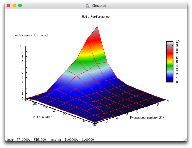
Because of the constant height of the parallel form the algorithm is very good scalable for the shared memory implementation. But the usage of the distributed memory leads to the locality problems.
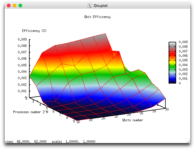
Let us perform a scalability analysis of a particular implementation of the single-qubit transform algorithm according to the scalability methodology with the use of the Lomonosov supercomputer[4] installed at the Research Computing Center of Moscow State University.
- the number of processors [4 : 512] with the powers of 2 step;
- the number of qubits [16 : 32] with step 2.
- minimum 0.000003%;
- maximum 0.008%.
The following Figures illustrate the performance and efficiency of the chosen parallel implementation of the Cholesky algorithm, depending on the startup parameters.
for the efficiency are shown at Figure 2b. It can be seen, that efficiency is quite low, but it grows fast with the number of qubits and remains constant with simultaneous increasing of the number of processors and qubits.
The following parallel implementation of the algorithm was used: parallel impplementation of single-qubit transform.
2.5 Dynamic characteristics and efficiency of the algorithm implementation
The implementation of the algorithm used for the analysis is available here. All results were obtained on the "GraphIT!" supercomputer. For the experiments we used the Intel Xeon X5570 processors with 94 Gflops peak performance and the Gnu 4.4.7 compiler.
The CPU usage diagram shows that the average CPU usage during almost all the runtime of the program is about 50%. This fact shows high load, when 8 processes works on 8 processors without HyperThreading technology. It means, that the usage of all physical cores is near to 100%.
Diagram for the number of floating point operations per second shows high performane. The peak performance is 300 mln. flops, and about 70 mln. flops on average between nodes. This fact may indicate the disbalance of the computations with rather high performance.
The diagram for the number of L1 cache-misses shows a high number of misses (4 mln/sec for some processe and 1 mln/sec on average). It indicates the high intensity and locality, and the disbalance of computations among processors.
The diagram for the number of L3 cache-misses still shows rather high number of misses (1 mln/sec at the peek and 0.25 mln/sec on average). The of L1/L3 misses is about 4 and it is average for the class of the same tasks. This value also shows low locality of computations.
The diagram for the number of memory read operations shows low activity of memory reads. Because of the big number of working processes, the difference between peak and average value of the activity shows the computations are unbalanced. The activity is lower than for typical software of the same class.
The activity of write operations is low, as it can be expected.
The plot of the number of processes ready for the execution (LoadAvg) shows that this value remains constant and approximately equals 3 throughout the program run. This shows that the program is operating in a stable manner, with small number of processes on each node. It confirms the suggestion about the disbalance of computations and shows that some processes have low activity.
Overall, the data obtained from the monitoring system allows one to come to the conclusion that the program under study works with low efficiency, but with the load disbalance. So, the program can be possibly optimized by the improvement of the processors balance.
2.6 Conclusions for different classes of computer architecture
Because of the very high parallelization possibility, but low locality, the effective and good scalable parallel implementation of the algorithm can be achieved for the shared memory. But the usage of distributed memory leads to the efficiency problems and necessity of special tricks for the optimization. It may be noted, that this task is a very good test platform for the development of methods for the data intense tasks with bad locality.
2.7 Existing implementations of the algorithm
The algorithm is implemented (mostly serial versions) in different libraries for quantum information science and quantum computer simulation. For example: QLib, libquantum, QuantumPlayground, LIQUi|>.
3 References
- ↑ Kronberg D. A., Ozhigov Yu. I., Chernyavskiy A. Yu. Algebraic tools for quantum information. (In Russian)
- ↑ Preskill J. Lecture notes for physics 229: Quantum information and computation //California Institute of Technology. – 1998.
- ↑ Nielsen, Michael A., and Isaac L. Chuang. Quantum computation and quantum information. Cambridge university press, 2010.
- ↑ Voevodin Vl.V., Zhumatii S.A., Sobolev S.I., Antonov A.S., Bryzgalov P.A., Nikitenko D.A., Stefanov K.S., Voevodin Vad.V. The Lomonosov supercomputer in practice. Otkrytye Sistemy (2012) No. 7, 36-39.
