Dense matrix multiplication, locality
Primary author of this description: Vad.V.Voevodin (Section 2).
Contents
1 Links
The key implementation fragments which were used to obtain the quantitative assessment are presented here (Kernel*** functions, where *** represents the cycle order (e.g., KernelIJK)).
2 Locality of data and computations
2.1 Locality of implementation
2.1.1 Structure of memory access and a qualitative estimation of locality
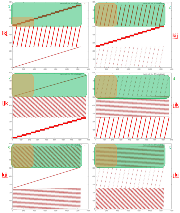
Fig.1 shows six memory call profiles for different variations of classical matrix multiplication (depending on the chosen order of cycles). Each profile has clearly visible segments for the three arrays used in the program. The order in which the three arrays are called is the same in all six variants; i.e., the interaction between the arrays is the same. In this case the differences in locality are determined by the inner construction of profile fragments for each individual array.
Based on the source code, we can see that there are a total of six different fragment types for individual arrays (these types are highlighted in green in Fig.1). Two clarifications need to be made: 1) The profile for the resulting array C is always twice as large because its elements are always addressed two times in a row; 2) if the innermost cycle calls array elements, calls to such elements are moved outside the innermost cycle (the cycle using a scalar variable instead).
It should also be noted also that these profile drawings are made as follows: the overall profile is built first, then only the part related to the respective array is left. The proportion of calls to one array can vary, therefore the frequency of calls in each picture can be substantially different, too.
Let’s look at each of the six fragments in more detail, taking Array C as an example.
“Fragment 1”. Fig.2 shows the beginning of Fragment 1 (hereinafter the beginning of a fragment corresponds to the orange area in Fig.1). The fragment structure is simple: a certain block of array elements is searched, then the search is repeated in a cycle. After that, the program moves to the next block of elements, and the same cyclic search is repeated.
If we look at the fragment in more detail (Fig.2), we can see that each search is in fact sequential, and each element is addressed twice.
As a result, we can conclude that Fragment 1 has a high spatial locality (due to the sequential search and the sequential change of blocks searched), and high temporal locality (due to each element being called twice and all calls to one element being confined to one search block).
“Fragment 2”. Fig.4 shows the beginning of Fragment 2. Clearly, the fragment also features a search of the array elements in a cycle, but in this case each array element is searched within one iteration, not just one block. A closer look at the iteration (Fig.5) reveals that the search is also sequential, and each element is addressed twice (as this is Array C).
This fragment also has a high spatial locality, but the temporal locality is lower than in Fragment 1. This is due to the fact that each iteration of the cycle goes through all of the array elements, not just an individual block, i.e. the interval between consecutive calls to the same element is larger.
“Fragment 3”. The beginning of this fragment is shown in Fig.6. The profile represents a consecutive search through all array elements. But a more detailed analysis shows that each element is addressed twice, with a few calls to other elements in-between. This is explained by the remark above about the recurring call being taken outside of the innermost cycle.
This fragment also has high spatial locality, but low temporal locality, as each element is only addressed twice.
“Fragment 4”. From the beginning of Fragment 4 it is clear that the profile again consists of a search through all array elements, though this time the search is not consecutive but with some interval. One can also notice that the search for each subsequent iteration begins at an element with a somewhat larger index than the previous iteration. In this case there is no need to view the profile in more detail, as this picture provides enough information.
Compared to the previous fragment, this profile has lower spatial locality, as there is a large interval between the elements searched, and very low temporal locality, as each iteration accesses new elements.
“Fragment 5”. Unlike the fragments described earlier, it is hard to draw any conclusions about the memory call structure by looking at the beginning of this fragment (Fig.8). But a more detailed look (Fig.9) shows that this profile is almost identical to the previous fragment. In fact, Fragment 5 actually consists of multiple iterations of Fragment 4.
Compared to Fragment 4, this fragment has almost the same spatial locality, but with higher temporal locality. The reason is the same in both cases – the same set of memory calls is repeated several times.
“Fragment 6”. This fragment, as shown in Fig.11 and Fig.12, also resembles Fragment 5, but with one significant difference. Fragment 5 contains several repetitions of Fragment 4, which in turn contains several iterations, and each iteration within Fragment 4 accesses different elements (with the starting element index being increased by 1 for each iteration). In Fragment 6, the same iterations are performed but in a different order. First, all iterations starting with the same element are performed; then all iterations starting with the next element, etc.
This fragment has higher spatial and temporal locality than Fragment 5, as calls to the same elements are located closer to one another in the profile.
In summary, we can say that Fragments 5 and 6 have the lowest locality in general. Fragment 4 also has lower locality, but contains fewer memory calls and therefore contributes less to the overall memory call profile. This allows us to determine that the least efficient variations from the viewpoint of working with memory are kji and jki, as they contain both Fragment 5 and Fragment 6. The second best are the ijk and jik variations – they each contain one such fragment. And the best variations are ikj and kij.
2.1.2 Quantitative estimation of locality
Launch conditions are described here.
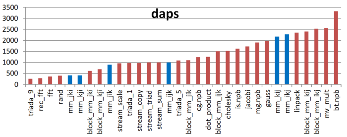
The first estimate is based on daps, which assesses the number of memory access operations (reads and writes) per second. Similar to flops, this tool is used to evaluate memory access performance rather than locality. But it is still a good source of information, particularly in combination with the next estimate – cvg.
Fig.13 shows the daps values for implementations of common algorithms sorted in ascending order (larger daps values generally indicate higher performance). You can see that the kij and ikj versions are predictably the most efficient. The jik and ijk variations show substantially lower results, though nearly equal to each other. As expected, kji and kji exhibit the worst performance.
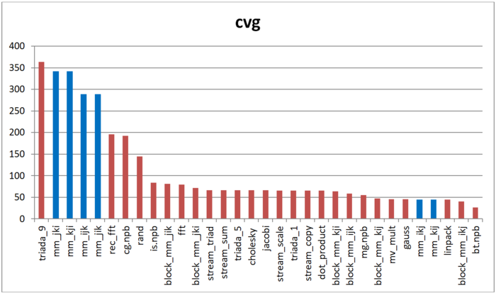
The second tool – cvg – is intended to obtain a more machine-independent locality assessment. It determines how often a program needs to pull data to cache memory. Respectively, the smaller the cvg value, the less frequently data needs to be called to cache, and the better the locality.
Fig.14 shows cvg values for the same set of implementations, sorted in descending order (a lower cvg generally indicates higher locality). You can see that the comparison of cvg results is generally the same as the daps assessment.


